Steam-gas displacement and gravity oil drain composite exploiting method

A technology of gravity drainage and production method, which is applied in well completion and oil recovery technology, oil field drilling, and can solve problems such as insufficient steam generator injection capacity and insufficient water resources at sea

Active Publication Date: 2014-07-23
CHINA UNIV OF PETROLEUM (BEIJING)
View PDF6 Cites 32 Cited by
  • Summary
  • Abstract
  • Description
  • Claims
  • Application Information

AI Technical Summary

Problems solved by technology

[0009] In order to solve the above problems, the present invention provides a composite recovery method of steam-gas displacement and gravity drainage. reservoirs, thin oil layers with a thickness of only a fe

Method used


Image

  • Steam-gas displacement and gravity oil drain composite exploiting method
  • Steam-gas displacement and gravity oil drain composite exploiting method
  • Steam-gas displacement and gravity oil drain composite exploiting method

Examples


Embodiment 11

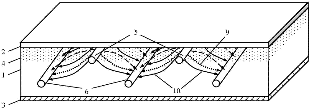
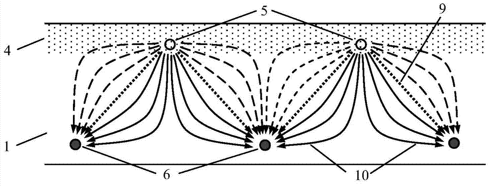
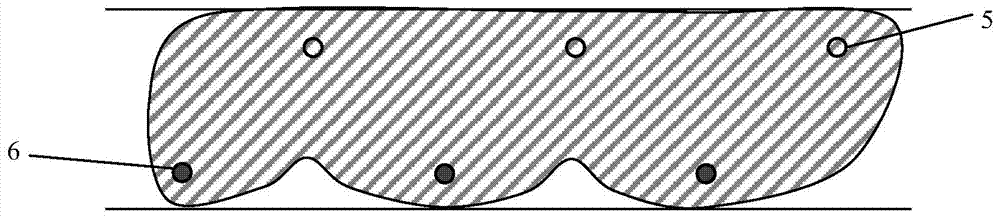
[0086] refer to figure 1 and figure 2 , in this example, steam-N 2 The combined recovery method of displacement and gravity drainage can exploit horizontal, homogeneous and thick heavy oil reservoirs.

[0087] A 750m×500m×30m horizontal, homogeneous, thick heavy oil reservoir 1a, the top of the reservoir is the overburden 2, the bottom is the underburden 3, the top depth of the reservoir is 1000m, and the thickness is 30m. The specific reservoir The parameters are shown in Table 1. A homogeneous reservoir geological model with 15 × 100 × 15 grids is established. The size of the grid in the X direction is 50 m, the size of the grid in the Y direction is 5 m, and the size of the grid in the Z direction is 2 m. Steam-N 2 The reservoir model of displacement and gravity drainage combined recovery is as follows: image 3 As shown, the three injection wells 5 and the three production wells 6 are all horizontal wells, the horizontal section (that is, the horizontal completion se...

Embodiment 12

[0116] A Steam-N 2 The combined recovery method of displacement and gravity drainage is the same as in Example 1.1, except that the thickness of the reservoir is 50m, the injection well 5 is arranged 25m below the top of the reservoir, the production well 6 is arranged 5m above the bottom of the reservoir, and the injection well The vertical distance between the injection well and the production well is 20m, the horizontal distance between the injection well and the production well is 50m, and the horizontal section length of the injection well and the production well is 500m.

Embodiment 13

[0118] A Steam-N 2 The combined recovery method of displacement and gravity drainage is the same as in Example 1.1, except that the reservoir depth is 220m, the original reservoir pressure is 2MPa, the crude oil viscosity is 235 centipoise, the injection well 5 is arranged 5m below the top of the reservoir, and the production well 6 is arranged 5m above the bottom of the reservoir, the vertical distance between the injection well and the production well is 20m, the horizontal distance between the injection well and the production well is 70m, and the length of the horizontal section of the injection well and the production well is 300m.


PUM

PropertyMeasurementUnit
Horizontal permeabilityaaaaaaaaaa

Abstract

The invention provides a steam-gas displacement and gravity oil drain composite exploiting method. According to the method, at least one horizontal well or a row of vertical wells close to the top of an oil pool are adopted as injection well sets, horizontal wells with the number same as that of wells in the injection well sets or with one more well are close to the bottom of the oil pool and are used as extraction well sets, the injection well sets and the extraction well sets are arranged in parallel in a non-direct-facing mode, and lower extraction wells are located in the middle portions of two upper injection wells. Steam huff and puff or steam and gas composite huff and puff are carried out on the injection wells and the extraction wells at the same time or in sequence, heat communication is built between the injection wells and the extraction wells to low the formation pressure, then high-temperature steam and non-condensation gas are injected into the injection wells at the same time or in an alternating mode, the injected steam seeps in the oil pool and heats the oil pool, the steam is condensed into hot water at the same time, and the gas expands a heating cavity, lowers heat loss and increases the pressure of the oil pool, so that crude oil flows to the extraction wells and is extracted under the composite effect of pressure displacement and gravity oil drain.

Description

technical field [0001] The invention belongs to oil field drilling, well completion and oil production technology, in particular to a combined production method of steam-gas displacement and gravity drainage. Background technique [0002] The steam and gas push (SAGP for short) introduced in the literature The Steam and Gas Push (SAGP). (R.Butler.Journal of Canadian Petroleum Technology, 1999,38(3):54-61.) is A heavy oil recovery method first proposed by Roger Butler. This method adopts a method similar to Steam Assisted Gravity Drainage (SAGD) and uses two horizontal wells facing up and down in parallel. The upper part is the injection well and the lower part is the production well. The distance between the injection well and the top of the oil layer is generally 15m, that is to say, the thickness of the oil layer is generally more than 17m-20m. In the SAGP process, a higher concentration of non-condensable gas is injected into the steam chamber, so that the gas accumulat...

Claims


Application Information

Patent Timeline
IPC IPC(8): E21B43/24
Inventor 钟立国于镝孙永涛林涛刘海涛孙玉豹王少华
Owner CHINA UNIV OF PETROLEUM (BEIJING)
Why Eureka
Try Eureka