
Continuously supplying device of liquefied carbon dioxide fluid

A liquid carbon dioxide and supply device technology, applied in the direction of gas/liquid distribution and storage, container discharge methods, equipment loaded into pressure vessels, etc., to achieve continuous and stable output, low energy consumption, and wide application range

Active Publication Date: 2014-07-23
SHAANXI NORMAL UNIV
View PDF6 Cites 2 Cited by
  • Summary
  • Abstract
  • Description
  • Claims
  • Application Information

AI Technical Summary

Problems solved by technology

[0005] The technical problem to be solved by the present invention is to overcome the shortcomings of the above-mentioned carbon dioxide fluid supply device, and provide a continuous supply device for liquid carbon dioxide fluid with reasonable design, easy operation, low energy consumption and wide application range

Method used


Image

  • Continuously supplying device of liquefied carbon dioxide fluid
  • Continuously supplying device of liquefied carbon dioxide fluid
  • Continuously supplying device of liquefied carbon dioxide fluid

Examples


Embodiment 1

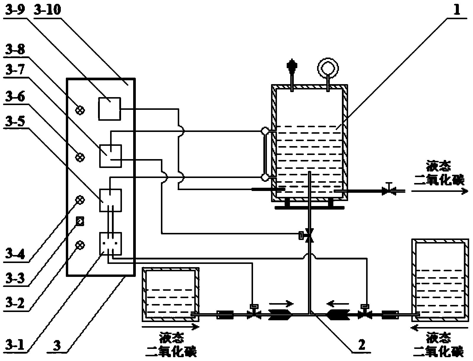
[0020] exist figure 1 Among them, the continuous supply device of the liquid carbon dioxide fluid in this embodiment is composed of a liquid carbon dioxide storage tank 1 , a liquid carbon dioxide bus 2 , and a controller 3 connected together.

[0021] A controller 3 is arranged on the left side, and a liquid carbon dioxide storage tank 1 and a liquid carbon dioxide busbar 2 are arranged on the right side. The liquid carbon dioxide storage tank 1 is connected to the controller through a wire, and the liquid carbon dioxide busbar 2 is connected to the controller through a wire. , communicate with the liquid carbon dioxide storage tank 1 through pipelines.

[0022] The controller 3 of this embodiment consists of a low liquid level controller 3-1, a right liquid carbon dioxide tank alarm 3-2, a reset switch 3-3, a left liquid carbon dioxide tank alarm 3-4, and a left and right road switcher 3-5 , liquid inlet solenoid valve indicator light 3-6, high liquid level controller 3-7, ...

Embodiment 2

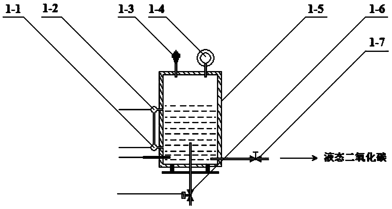
[0027] Figure 4 A schematic structural diagram of Embodiment 2 of the liquid carbon dioxide storage tank 1 is given. exist Figure 4 Among them, the liquid carbon dioxide storage tank 1 of this embodiment is composed of a temperature sensor 1-1, a liquid level sensor 1-2, a safety valve 1-3, a pressure gauge 1-4, a main tank body 1-5, and a liquid inlet solenoid valve 1 -6, the liquid outlet valve 1-7, the coolant inlet pipe 1-8, and the coolant outlet pipe 1-9 are connected to form. The main tank body 1-5 of the present embodiment is a sandwich tank body, and the cooling liquid inlet pipe 1-8 is installed by screw connection under the right side of the main tank body 1-5, and the cooling liquid inlet pipe 1-8 is connected with the main tank body. 1-5 interlayer is interconnected, and the right side of the main tank 1-5 is threadedly installed with a coolant outlet pipe 1-9, and the coolant outlet pipe 1-9 communicates with the main tank 1-5 interlayer. In this embodiment,...


PUM


Abstract

The invention discloses a continuously supplying device of liquefied carbon dioxide fluid. The continuously supplying device comprises a controller on the left side, as well as a liquefied carbon dioxide storage regulating tank and a liquefied carbon dioxide bus bar on the right side, wherein the liquefied carbon dioxide storage regulating tank is connected with the controller through a lead; the liquefied carbon dioxide bus bar is connected with the controller through a lead and connected with the liquefied carbon dioxide storage regulating tank through a pipeline. The liquefied carbon dioxide bus bar adopts a left liquefied carbon dioxide tank and a right liquefied carbon dioxide tank which are arranged side by side, the controller controls the left liquefied carbon dioxide tank or the right liquefied carbon dioxide tank to alternatively convey liquefied carbon dioxide to the main tank body of the liquefied carbon dioxide storage regulating tank so as to continuously and stably output liquefied carbon dioxide. The continuously supplying device of the liquefied carbon dioxide fluid has the advantage of being reasonable in design, reliable in performance, convenient to operate, low in energy consumption and wide in application scope and can be applied to continuous supply of liquefied carbon dioxide fluid in industial productions and scientific researches.

Description

technical field [0001] The invention belongs to the technical field of supply equipment or devices for carbon dioxide fluid, and in particular relates to a continuous supply device for liquid carbon dioxide fluid. Background technique [0002] Supercritical carbon dioxide has become a recognized green medium, and has been increasingly used in industrial production and scientific research because of its unique advantages. At present, the flow process involving supercritical carbon dioxide technology mainly includes supercritical carbon dioxide extraction, drying, dyeing and foaming, as well as some chemical reactions and material synthesis in supercritical carbon dioxide. The normal operation of the above flow processes depends on the continuous and stable supply of carbon dioxide fluid. Severe fluctuations or interruptions in the supply of carbon dioxide fluid will have a serious negative impact on production and scientific research, resulting in the inability to continue t...

Claims


Application Information

Patent Timeline
IPC IPC(8): F17C5/02F17C13/02F17C13/04
Inventor 陈建刚关红飞刘昭铁王明晞沈淑坤刘忠文江金强郝郑平
Owner SHAANXI NORMAL UNIV
Learn More