Dry heat rock photothermal coupling power generation system with heat storage function and control method system thereof
A technology of photothermal coupling and power generation system, which is applied in geothermal power generation, solar thermal power generation, machines/engines, etc., can solve the problem that hot dry rock and solar heat cannot efficiently utilize investment, low temperature of hot dry rock power generation, and small footprint Large and other problems, to achieve the effect of reducing the scale of the photothermal mirror field, saving the occupied area, and stabilizing the system
- Summary
- Abstract
- Description
- Claims
- Application Information
AI Technical Summary
Problems solved by technology
Method used
Image
Examples
Embodiment 1
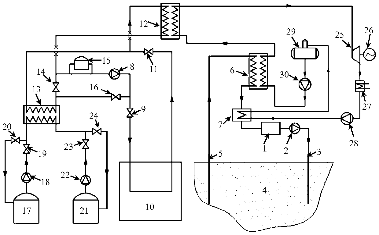
[0049] The circulating working medium and thermal storage working medium in the photothermal subsystem are different, see figure 1 The power generation system includes: hot dry rock circulation subsystem consisting of hot dry rock buffer tank 1, injection pump 2, hot dry rock injection well 3, hot dry rock recovery well 5, regenerator 7, etc.; photothermal working medium pump 8 , heat collector 10, heat storage heat exchanger 13, heat tank 17, cold tank 21, etc.; , feed water pump 30 and other equipment to form a steam generation sub-system. The three subsystems are coupled through the low-temperature heat exchanger 6 and the high-temperature heat exchanger 12 to form a combined power generation system to achieve the purpose of continuously and stably outputting electric energy.
[0050] For the hot dry rock circulation subsystem, the circulating working medium can be water, supercritical CO 2 , ammonia, etc. No matter what kind of circulating working fluid is used, the syst...
Embodiment 2
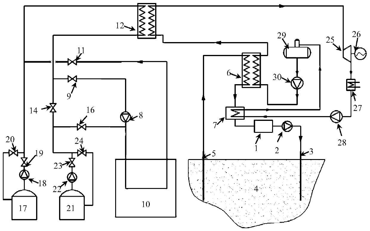
[0059] If the circulating working fluid and the heat storage medium are the same, the system such as figure 2 shown. compared to figure 1 system shown, figure 2 In the system shown, only the branches where the heat storage heat exchanger 13, the photothermal buffer tank 15, and the third valve 14 are located are reduced, and there are no other differences.
[0060] Assume that the circulating working fluid is molten salt.
[0061] Wherein, the outlet of heat collector 10 is provided with second valve 11, and the outlet of second valve 11 is divided into two roads, one road is connected with the first inlet of high temperature heat exchanger 12; The main pipeline of the hot tank 17 is provided with a hot tank molten salt pump 18 and a hot tank main circuit valve 19, and the bypass pipeline of the hot tank 17 is provided with a hot tank bypass valve 20.
[0062] The first outlet of the high-temperature heat exchanger 12 is divided into two routes, one of which is connected...
PUM
 Abstract
Description
Claims
Application Information
 - R&D
- Intellectual Property
- Life Sciences
- Materials
- Tech Scout
- Unparalleled Data Quality
- Higher Quality Content
- 60% Fewer Hallucinations
Browse by: Latest US Patents, China's latest patents, Technical Efficacy Thesaurus, Application Domain, Technology Topic, Popular Technical Reports.
© 2025 PatSnap. All rights reserved.Legal|Privacy policy|Modern Slavery Act Transparency Statement|Sitemap|About US| Contact US: help@patsnap.com


