Novel multi-angle and multi-mode quick switching circular optical illumination microscopic imaging system

A fast-switching, micro-imaging technology, applied in fluorescence/phosphorescence, material excitation analysis, etc., can solve the problems of inability to realize fluorescence imaging mode conversion, difficulty in measuring imaging depth, and inability to perform quantitative analysis, etc. Convenient, High-Resolution Effects

Inactive Publication Date: 2014-07-23
ZHEJIANG UNIV
View PDF5 Cites 15 Cited by
  • Summary
  • Abstract
  • Description
  • Claims
  • Application Information

AI Technical Summary

Problems solved by technology

[0005] HILO (Highly inclined laminated optical) is generated when the incident angle is about to enter TIRF. The noise ratio is very small during imaging, and the signal-to-noise ratio can reach several times that of EPI. It is very suitable for observing the activities of living cells, but it is difficult compared with TIRF Depth of imaging is determined, quantitative analysis is not possible
[0006] Commercial total internal reflection fluorescence microscopes currently on the market do not have the function of freely switching the angle and size of the TIRF ring, nor can it achieve convenient fluorescence imaging mode switching

Method used


Image

  • Novel multi-angle and multi-mode quick switching circular optical illumination microscopic imaging system
  • Novel multi-angle and multi-mode quick switching circular optical illumination microscopic imaging system
  • Novel multi-angle and multi-mode quick switching circular optical illumination microscopic imaging system

Examples


Embodiment

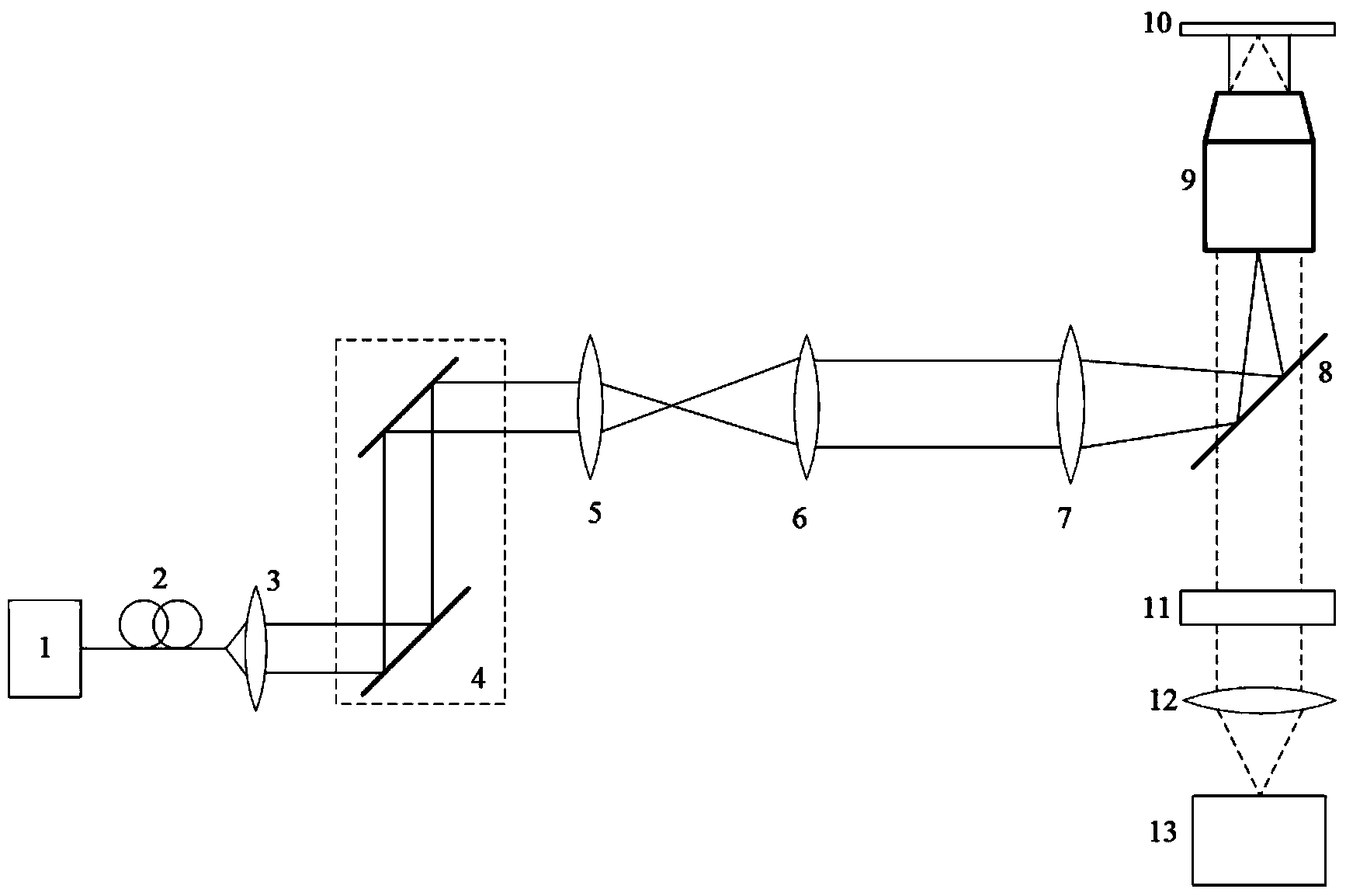
[0047] First, the laser light is emitted from the laser produced by Melles Griot Company, and is imported into the collimating lens of Thornlabs Company through a single-mode fiber to complete the collimation; the collimated beam enters the scanning galvanometer system of Thornlabs Company for optical path deflection, and then enters Thornlabs Company Focusing is performed in the company's scan lens. The beam emitted by the scanning lens is expanded by the first field mirror, and then emitted in parallel, after being focused and reflected by the focusing mirror and dichroic mirror of Thornlabs, the beam is focused on the objective lens of the TIRF microscope produced by OLYMPUS and projected on the sample stage. . The signal light emitted by the sample to be tested is collected by the TIRF microscope objective lens, first passes through the dichromatic mirror, then passes through the filter to filter out stray light, and is focused by the second field lens, and finally collect...


PUM


Abstract

The invention discloses a novel multi-angle and multi-mode quick switching circular optical illumination microscopic imaging system which comprises a laser, a single mode fiber, a collimating lens, a scanning galvanometer, a scanning lens, a first field lens, a focus lens, a dichroic mirror, a total internal reflection fluorescence (TIRF) microscope objective, a sample platform, a filter, a second field lens and a detector, wherein the single mode fiber, the collimating lens and the scanning galvanometer are sequentially located on an optical axis of an outgoing beam of the laser; the scanning lens, the first field lens, the focus lens and the dichroic mirror are sequentially located on an optical axis of an outgoing beam of the scanning galvanometer; the TIRF microscope objective and the sample platform are sequentially located on an optical axis of a reflected beam of the dichroic mirror; the filter, the second field lens and the detector are sequentially arranged on an optical axis of a transmission beam of the dichroic mirror; the sample platform is arranged on a focus plane of the TIRF microscope objective; a collecting hole of the detector is formed in a focus plane of the second field lens. On the basis of TIRF, the microscopic imaging system disclosed by the invention realizes microscopic experimental observation which is convenient and rapid, high in resolution and low in noise.

Description

technical field [0001] The invention belongs to the field of new microscopic methods, and in particular relates to a novel multi-angle multi-mode fast-switching annular optical illumination microscopic imaging system. Background technique [0002] Total internal reflection fluorescence microscope (TIRFM) utilizes the characteristics of evanescent waves generated on the other side of the medium after total reflection of light to excite fluorescent molecules to observe the extremely thin area of ​​the fluorescent calibration sample. The dynamic range of observation is usually in the range of Below 200nm. Because of the exponential attenuation of the excitation light, only the sample area very close to the total reflection surface will produce fluorescence reflection, which greatly reduces the interference of background light noise on the observation specimen, and can help researchers obtain high-quality imaging quality and reliable observation data. Therefore, this technique ...

Claims


Application Information

Patent Timeline
Patent Type & Authority Applications(China)
IPC IPC(8): G01N21/64
Inventor 许迎科南迪樊剑南孙永红刘旭匡翠芳
Owner ZHEJIANG UNIV
Why Eureka
Try Eureka