Hollow plastic optical fiber and optical cable

A plastic optical fiber and hollow core technology, applied in the field of LED lighting, can solve the problems of low transmission bandwidth and speed, incompatibility, and difficulty in achieving higher speeds, and achieve high market application value, high transmission speed, and low The effect of transmission attenuation

Active Publication Date: 2014-07-23
SHEN ZHEN SINNO OPTOELECTRONICS TECH CO LTD
View PDF7 Cites 11 Cited by
  • Summary
  • Abstract
  • Description
  • Claims
  • Application Information

AI Technical Summary

Problems solved by technology

[0016] However, the existing plastic optical fiber has the following disadvantages: a. solid core material structure, light attenuation is large, because the step type plastic optical fiber adopts solid plastic (polymer) as the optical fiber core, its light transmittance is not ideal, resulting in Larger optical attenuation, the attenuation of the step-type plastic optical fiber produced in Japan is basically 150-200dB / km, while the attenuation of the domestic step-type plastic optical fiber is basically about 200-250dB / km, which can be less than 200dB / km rare
c. The transmission bandwidth and rate are not high. The data transmission rate of the step-type plastic optical fiber can reach 100Mb / s*100m, but it is difficult to achieve a higher rate.
d. It is not compatible with the quartz fiber system. The step-type plastic optical fiber can only transmit visible light, and the infrared light transmitted by the mature quartz fiber system is greatly attenuated. Therefore, the step-type plastic fiber cannot be compatible with the quartz fiber system. The docking must pass Converters are not only inconvenient, but also increase the cost of

Method used


Image

  • Hollow plastic optical fiber and optical cable
  • Hollow plastic optical fiber and optical cable
  • Hollow plastic optical fiber and optical cable

Examples


Embodiment Construction

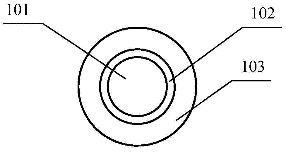
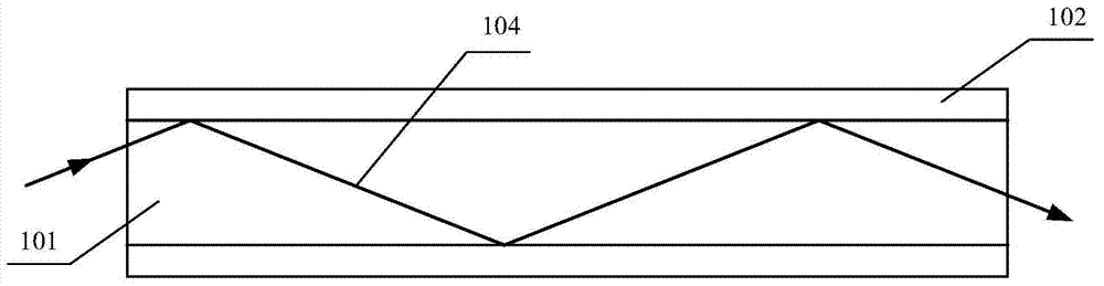
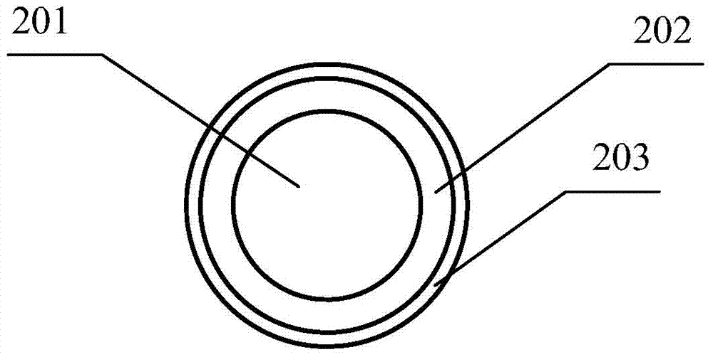
[0036] In order to facilitate the understanding of the present invention, the present invention will be described in more detail below in conjunction with the accompanying drawings and specific embodiments. Preferred embodiments of the invention are shown in the accompanying drawings. However, the present invention can be implemented in many different forms and is not limited to the embodiments described in this specification. On the contrary, these embodiments are provided to make the understanding of the disclosure of the present invention more thorough and comprehensive.

[0037] It should be noted that when an element is referred to as being “fixed” to another element, it can be directly on the other element or there can also be an intervening element. When an element is referred to as being "connected to" another element, it can be directly connected to the other element or intervening elements may also be present. The terms "vertical", "horizontal", "left", "right" and...


PUM


Abstract

The invention discloses a hollow plastic optical fiber and an optical cable, wherein the hollow plastic optical fiber is provided with a coating layer, a transition layer and a hollow core layer; the hollow core layer is hollow; the refractive index of the transition layer is more than that of the coating layer. Through adopting the above scheme, the hollow plastic optical fiber adopts a hollow design, so that the transmission attenuation of optical signals is greatly reduced, the limitation that the plastic optical fiber only can transmit visible light is broken through, the plastic optical fiber can transmit full-spectrum light and is completely compatible with an existing optical fiber system for use; the production cost is reduced so as to be easy to industrialize; the transmission distance is much longer, the transmission rate is much higher, and the deficiencies of an existing step type plastic optical fiber are overcome; therefore, the hollow plastic optical fiber can completely substitute the existing communication-level step type plastic optical fiber but also can substitute a copper network cable, the effect and purpose of saving copper resources, saving energy and protecting environment are achieved, and very high market application value is provided.

Description

technical field [0001] The invention relates to LED lighting, in particular to a hollow-core plastic optical fiber and an optical cable. Background technique [0002] Plastic Optical Fiber (POF), also known as polymer optical fiber and polymer optical fiber, is composed of a transparent polymer core layer with a high refractive index and a transparent polymer cladding layer with a low refractive index, and is especially suitable for making communication It is used with plastic optical fiber, which is a kind of optical fiber made of high transparent polymer material developed in the past two decades. It is a low-carbon and environmentally friendly product made of polymer material. It has a wide range of application requirements in the field of information transmission. It has been included in the national "New Material Industry "Twelfth Five-Year" Development Plan", and its industry development direction is fully in line with the national strategic emerging industry developme...

Claims


Application Information

Patent Timeline
Patent Type & Authority Applications(China)
IPC IPC(8): G02B6/032G02B6/44
Inventor 胡卫明陈明
Owner SHEN ZHEN SINNO OPTOELECTRONICS TECH CO LTD
Why Eureka
Try Eureka