Three-port router based on planar optical waveguide technology and manufacturing method thereof

A planar optical waveguide and router technology, applied in the direction of optical waveguide light guide, light guide, optics, etc., can solve the problems of large chip size, large occupied area, increased control and process difficulty, etc., and achieve small size, high integration, and manufacturing low cost effect

Active Publication Date: 2014-07-23
UNITED MICROELECTRONICS CENT CO LTD
View PDF4 Cites 9 Cited by
  • Summary
  • Abstract
  • Description
  • Claims
  • Application Information

AI Technical Summary

Problems solved by technology

In 2008, S.Nicolás of Cornell University took the lead in realizing a four-port thermal-optical router by using a combination of multi-microring optical switches [12], which can actually achieve non-blocking data communication between four cores. In 2010, IBM's M. Yang and others announced the realization of the M-Z broadband router based on the electro-optic effect. This router uses six 2×2 electro-optic switches and more than a dozen cross waveguides, and the working bandwidth reaches 7nm, but the chip size is large, reaching 300×1600μm2
[0004] From the perspective of the complexity of optical waveguide routers, currently reported four-port optical waveguide routers generally require the use of multiple interferometric optical switches. Taking the 4-port optical router of M.Yang reported by IBM as an example, six M-Z Type optical switch, occupying a large area and increasing the difficulty of control and process

Method used


Image

  • Three-port router based on planar optical waveguide technology and manufacturing method thereof
  • Three-port router based on planar optical waveguide technology and manufacturing method thereof
  • Three-port router based on planar optical waveguide technology and manufacturing method thereof

Examples


Embodiment Construction

[0029] The embodiments of the present invention are described in detail below. This embodiment is implemented on the premise of the technical solution of the present invention, and detailed implementation methods and specific operating procedures are provided, but the protection scope of the present invention is not limited to the following implementation example.

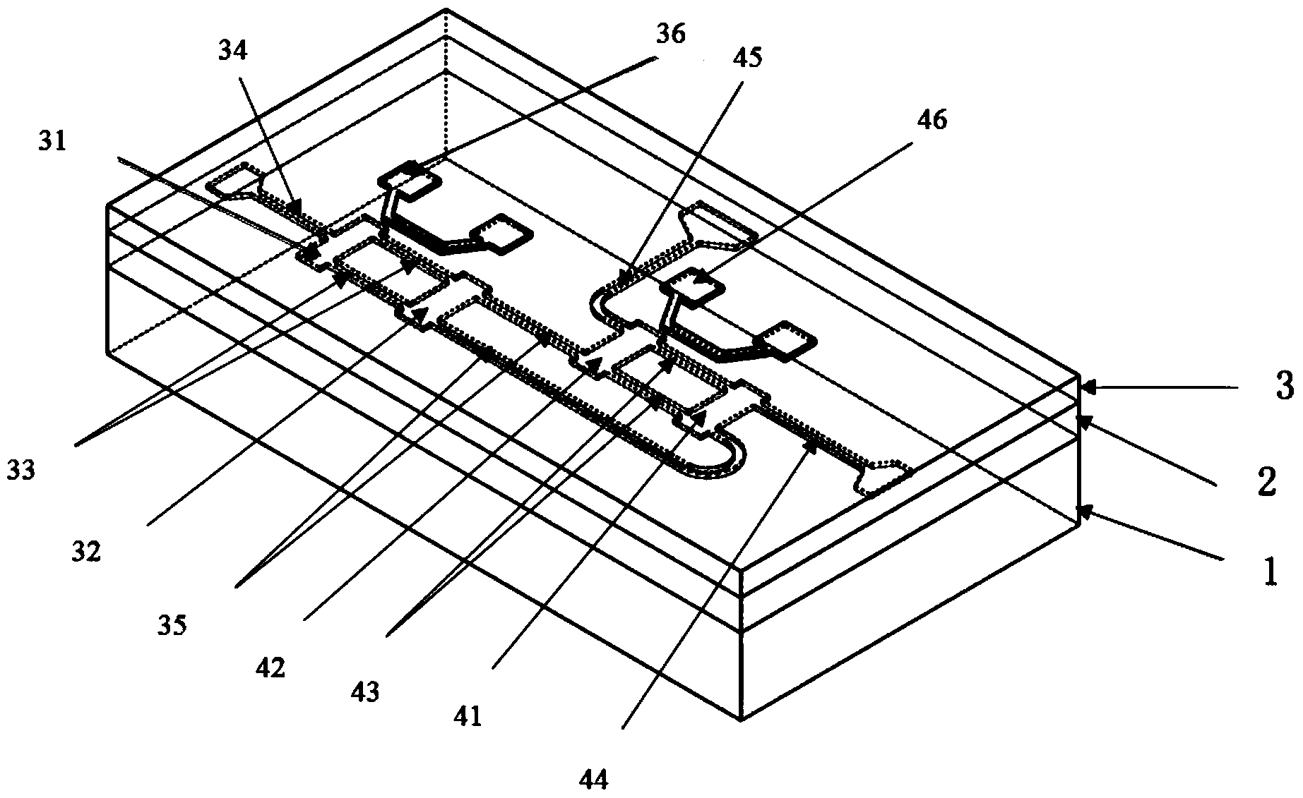
[0030] see figure 1 , a three-port router based on planar optical waveguide technology provided by the preferred embodiment of the present invention, includes a substrate layer 1, a core layer 2 and a cover layer 3 from bottom to top, and a 1X2 optical A switch and a 2X2 optical switch, the input port of the 1X2 optical switch is the first port Port1, and one of the input ports and one of the output ports of the 2X2 optical switch are the second port Port2 and the third port Port3 respectively. Preferably, the first port Port1, the second port Port2 and the third port Port3 are respectively located on three sides ...


PUM


Abstract

The invention discloses a three-port router based on the planar optical waveguide technology. The three-port router based on the planar optical waveguide technology comprises a substrate layer, a core layer and a covering layer from bottom to top. The core layer is provided with a 1*2 optical switch and a 2*2 optical switch which are combined in a cascaded mode. An input port of the 1*2 optical switch is a first port, and one input port and one output port of the 2*2 optical switch are a second port and a third port respectively. The first port, the second port and the third port are located in the side face of the router and serve as three exchange ports for data exchange. Two output ports of the 1*2 optical switch are connected with the other input port and the other output port of the 2*2 optical switch respectively. The router has the routing working mode and the broadcasting working mode. The invention further discloses a manufacturing method of the router. The three-port router based on the planar optical waveguide technology and the manufacturing method of the router have the advantages that the three exchange ports are in interconnection only through the two optical switches, the integration level is high, the structure is compact, and the working modes of the router can be controlled only through two phase shifters.

Description

technical field [0001] The invention relates to the field of planar optical waveguide integration, in particular to a three-port router based on planar optical waveguide technology and a preparation method thereof. Background technique [0002] In the past few decades, the development of integrated circuits has been based on the famous Moore's Law. The size of transistors has been shrinking, the integration of chips has been increasing geometrically, and the performance has been improving. But at the same time, Moore's Law is constantly being challenged. The idea of ​​increasing the performance of single-core processors by shrinking the transistor feature size has been stalled by a surge in power consumption and heat, increased interconnect delays, and increased design complexity. The solution of multi-core and many-core processors has gradually become an effective way to improve the performance of high-performance processors in the future. However, with the increase of the...

Claims


Application Information

Patent Timeline
Patent Type & Authority Applications(China)
IPC IPC(8): G02B6/125G02B6/13
Inventor 王皖君崔乃迪滕婕冯俊波郭进
Owner UNITED MICROELECTRONICS CENT CO LTD
Why Eureka
Try Eureka