A permanent magnet movable medium and low voltage circuit breaker driving device

A low-voltage circuit breaker and driving device technology, which is applied in the field of permanent magnet movable medium and low-voltage circuit breaker driving devices, can solve the problem of not being able to fully utilize high-current circuit shutdown, increasing the complexity of circuit breaker driving devices, and increasing the risk of circuit breaker switching etc., to achieve the effects of reducing the probability of high temperature burnout, simple structure, and improving mechanical reliability

Inactive Publication Date: 2016-08-17
EAST CHINA JIAOTONG UNIVERSITY
View PDF11 Cites 0 Cited by
  • Summary
  • Abstract
  • Description
  • Claims
  • Application Information

AI Technical Summary

Problems solved by technology

[0002] In the field of circuit breaker switches in power systems, the driving device of the traditional circuit breaker is composed of a mechanical spring or a mechanical latch, and there are many windings wound at the same time, which increases the complexity of the driving device of the circuit breaker, because the service life of the spring device has a certain number of years , and the mechanical snap-lock device requires a certain response time limit, both of which are prone to misoperation and immobility of the circuit breaker, and too many windings generate heat when a large driving current is applied, which causes the windings to be easily burned out , which also increases the risk of circuit breaker switching
[0003] The use of traditional electromagnetic circuit breakers also requires too many windings to be wound on the static iron core. Due to the limitation of temperature, it cannot be fully used for circuit shutdown with large currents.
[0004] At present, some substations and feeder protection fields in the power system use permanent magnet mechanisms to drive circuit breaker switches, but there are several disadvantages: (1) The structure is defective, and the permanent magnets are distributed on the static iron core, which increases the manufacturing process. Difficulty, it is necessary to slot into the static iron core to embed the permanent magnet; (2) The distance between the permanent magnet and the winding is relatively close, and when the temperature of the winding is too high, it is easy to cause degaussing; (3) The magnetic field generated by the permanent magnet is constant, and the magnetic flux The path is also fixed. When the magnetic flux path is opposite to the direction of the winding flux path of the current, it is also prone to serious degaussing, because the degaussing process is carried out continuously and stably with the winding current, which is bad consequences

Method used


Image

  • A permanent magnet movable medium and low voltage circuit breaker driving device
  • A permanent magnet movable medium and low voltage circuit breaker driving device
  • A permanent magnet movable medium and low voltage circuit breaker driving device

Examples


Embodiment Construction

[0025] The present invention will be further described below in conjunction with the accompanying drawings.

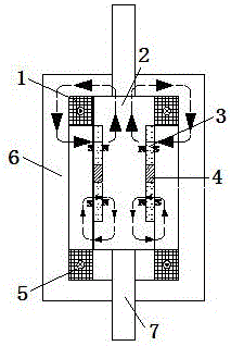
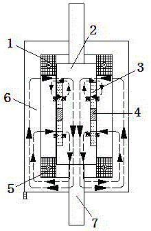
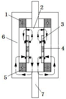
[0026] as attached Figures 1~5 As shown in the figure, a medium and low voltage permanent magnet movable circuit breaker driving device of the present invention includes an opening winding 1, a moving iron core 2, a permanent magnet 3, a fixing device 4, a closing winding 5, a static iron core 6, and a driving connecting rod 7 .

[0027] The opening and closing windings are respectively wound around the upper and lower parts of the static iron core 6.

[0028] The moving iron core 2 adopts the "I" shape structure design, the cross-sectional area of ​​the moving iron core is circular, and the cross-sectional diameter of the two ends of the moving iron core is larger than the cross-sectional diameter of the middle of the moving iron core, such as Figure 5 As shown, the inner diameter of the aluminum ring or permanent magnet of the fixing device is the inner diameter ...


PUM


Abstract

A movable medium-low-voltage circuit breaker drive device for permanent magnets is composed of a separating brake winding, movable iron cores, the permanent magnets, a fixing device, a closing winding, a static iron core and a driving connecting rod. The separating brake winding winds the upper portion of the static iron core, and the closing winding winds the lower portion of the static iron core. The movable iron cores are of an I-shaped structure. The permanent magnets and the fixing device are embedded in the movable iron cores in a surrounding mode, the fixing device is embedded in the middle of the movable iron cores, and the two permanent magnets are embedded in the movable iron cores at the two ends of the fixing device respectively. The driving connecting rod and the movable iron cores are connected into a whole. According to the movable medium-low-voltage circuit breaker drive device, the permanent magnets are embedded in the movable iron cores, the permanent magnets and a winding magnetic field act together, the separating-closing transition process is simplified, and the limit steady state is obtained rapidly. The movable medium-low-voltage circuit breaker drive device can be used in protection of transformer substations of electrical power systems, rail traction substations and various feeders.

Description

technical field [0001] The invention relates to a permanent magnet movable medium and low voltage circuit breaker driving device, which belongs to the technical field of electric power system manufacturing. Background technique [0002] In the field of circuit breaker switches in power systems, the traditional drive device of the circuit breaker is composed of mechanical springs or mechanical locks, and many windings are wound at the same time, which increases the complexity of the circuit breaker drive device. Since the service life of the spring device has a certain number of years , and the mechanical locking device needs a certain response time, both of which are prone to the malfunction and immobility of the circuit breaker. Too many windings generate heat when a large driving current is applied, which leads to the windings being easily burned out. , which also increases the risk of circuit breaker switching. [0003] The use of traditional electromagnetic circuit brea...

Claims


Application Information

Patent Timeline
Patent Type & Authority Patents(China)
IPC IPC(8): H01H71/10H01H71/32H01H71/68
Inventor 彭春华王奎
Owner EAST CHINA JIAOTONG UNIVERSITY
Why Eureka
Try Eureka