Shaping device and method for field emission electron source emitter tip

An electron source and field emission technology, which is applied in the manufacture of circuits, electrical components, electrode systems, etc., can solve the problems of large emission beam current and inability to work stably, and achieve large emission current, high angular current density, and concentrated emission direction Effect

Active Publication Date: 2014-07-23
PEKING UNIV
View PDF2 Cites 5 Cited by
  • Summary
  • Abstract
  • Description
  • Claims
  • Application Information

AI Technical Summary

Problems solved by technology

[0007] Aiming at the problem that the tip of a field emission electron source emitter with a small radius of curvature cannot work stably at high temperature after electrochemical corrosion and surface oxidation treatment, the present invention proposes a shaping device and a shaping method for the tip of a field emission electron source emitter, After the tip of the field emission electron source emitter is shaped, its tip forms a stable emission surface. The stable emission surface can make the electron beam emitted by the field emission electron source have a concentrated emission direction, and the larger emission beam and Stable beam emission and other characteristics

Method used


Image

  • Shaping device and method for field emission electron source emitter tip
  • Shaping device and method for field emission electron source emitter tip
  • Shaping device and method for field emission electron source emitter tip

Examples


Embodiment Construction

[0039] The present invention will be further described through the embodiments below in conjunction with the accompanying drawings.

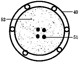
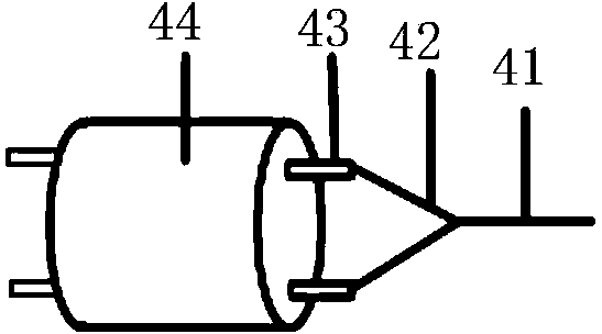
[0040] Such as figure 2 As shown, the field emission electron source emitter tip shaping device of this embodiment includes: a vacuum chamber 1, a vacuum pumping system 2, a vacuum degree measurement system 3, an electron gun assembly 4, a power supply system 5 and an electron beam imaging system 6; Wherein, the lower surface of the vacuum chamber 1 is connected to the vacuum pumping system 2 through the flange port 20, and the upper surface is connected to the vacuum degree measuring system 3 through the flange port 30; the electron gun assembly 4 is installed in the vacuum chamber 1 through the electron gun flange port 40 and connected to the power system 5 outside the vacuum chamber through conductive leads; on the surface of the vacuum chamber opposite to the electron gun assembly, an electron beam imaging system 6 is installed through the ...


PUM


Abstract

The invention discloses a shaping device and method for a field emission electron source emitter tip. The shaping device comprises a vacuum chamber, a vacuum pumping system, a vacuum degree measuring system, an electronic gun assembly, a power source system and an electron beam imaging system. The method comprises the steps that the field emission electron source emitter tip is heated to be passivated, a critical electric field is applied to an anode to form field emission, the balance, on the surface, between the surface tension of the emitter tip and the electric field force produced by the additional electric field is achieved, and therefore shaping is achieved; after the field emission electron source emitter tip is shaped, a stable emission surface is formed on the emitter tip. The stable emission surface can make electronic beam current emitted by a field emission electron source have the advantages that the emission current is large, emission directions are concentrated, the density of angle current is high, monochromaticity is good, and beam current emission is stable.

Description

technical field [0001] The invention relates to a field emission electron source, in particular to a field emission electron source emitter tip shaping device and a shaping method thereof. Background technique [0002] As an important tool for human beings to explore the microcosm, the field emission electron microscope is widely used in many fields such as material science, life science, semiconductor industry, geology, energy, medical treatment, and pharmaceuticals with its unique high-resolution and analytical performance. It plays a huge role in scientific research and industrial production. [0003] The field emission electron source is one of the core components of the field emission electron microscope. Its performance determines the main electron optical performance parameters in the field emission electron microscope, which includes the emission angular current density of the electron gun, the total emission beam current of the electron beam, and the energy dispersi...

Claims


Application Information

Patent Timeline
Patent Type & Authority Applications(China)
IPC IPC(8): H01J9/02
Inventor 徐军刘亚琪王朋博袁明艺饶先拓陈莉朱瑞
Owner PEKING UNIV
Why Eureka
Try Eureka