
Storage type ion source

An ion source and ionization chamber technology, applied in the field of vacuum electronics, can solve the problems of poor ion beam current uniformity and stability, limiting the development of ion source technology, and large differences in ion energy, achieving small energy dispersion and small emission area, the effect of miniaturization

Active Publication Date: 2021-04-02
LANZHOU INST OF PHYSICS CHINESE ACADEMY OF SPACE TECH
View PDF13 Cites 1 Cited by
  • Summary
  • Abstract
  • Description
  • Claims
  • Application Information

AI Technical Summary

Problems solved by technology

[0004] The trajectory controllability of the electron beam focusing introduced by the traditional electron collision ion source is poor, and the initial position of the initial ion generated by the electron collision is relatively scattered. and time difference
These problems limit the development of ion source technology, and also limit its application in the field of high-end measuring instruments or analytical instruments
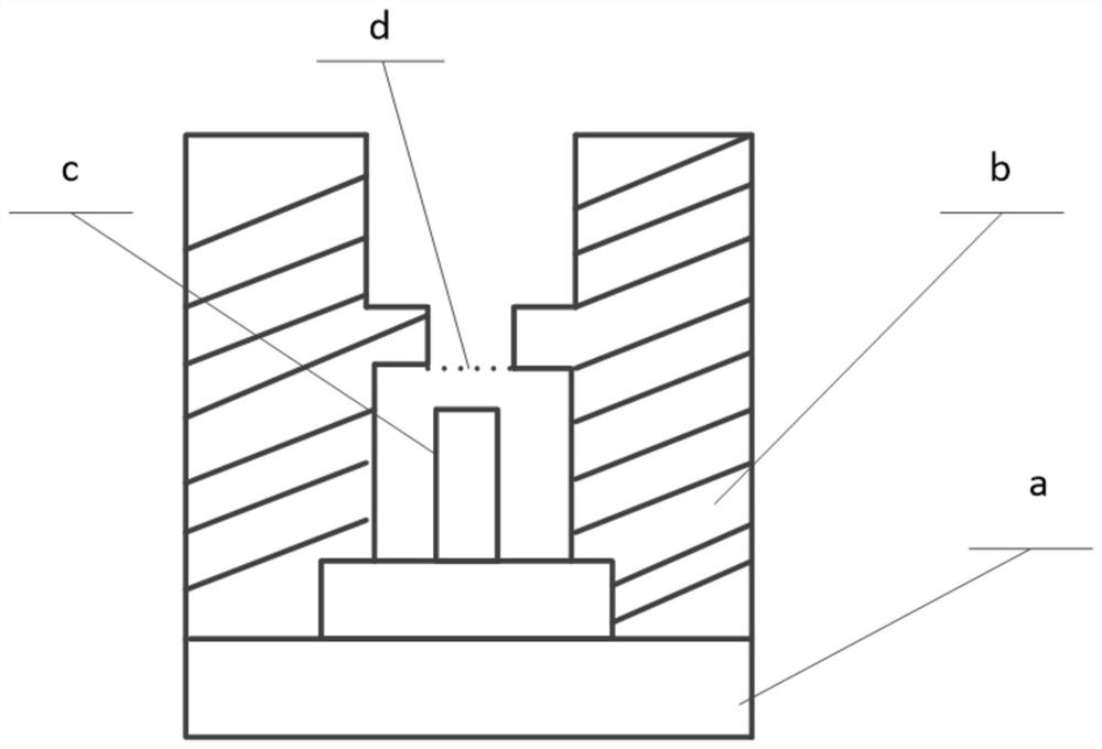
like figure 1 As shown, S.Sheridan et al. proposed a carbon nanotube cathode impact ionization source applied to a space mass spectrometer (see "S.Sheridan, M.W.Bardwell, A.D.Morse et al.A carbon nanotubeelectron impact ionization source for low- power, compact spacecraft massspectrometers.Advances in Space Research, 2012; 49: 1245), the electron source’s outgoing electron energy reaches hundreds of electron volts, and the carbon nanotube cathode area is 0.5mm 2 , the ionization efficiency is relatively low. After the electrons are extracted, they randomly collide with ionized gas molecules, and the ions are directly introduced into the mass analyzer. The uniformity and stability of the ion beam are poor.

Method used


Image

  • Storage type ion source
  • Storage type ion source
  • Storage type ion source

Examples


Embodiment Construction

[0024] In order to enable those skilled in the art to better understand the solution of the present application, the technical solution in the embodiment of the application will be clearly and completely described below in conjunction with the accompanying drawings in the embodiment of the application. Obviously, the described embodiment is only It is an embodiment of a part of the application, but not all of the embodiments. Based on the embodiments in this application, all other embodiments obtained by persons of ordinary skill in the art without creative efforts shall fall within the scope of protection of this application.

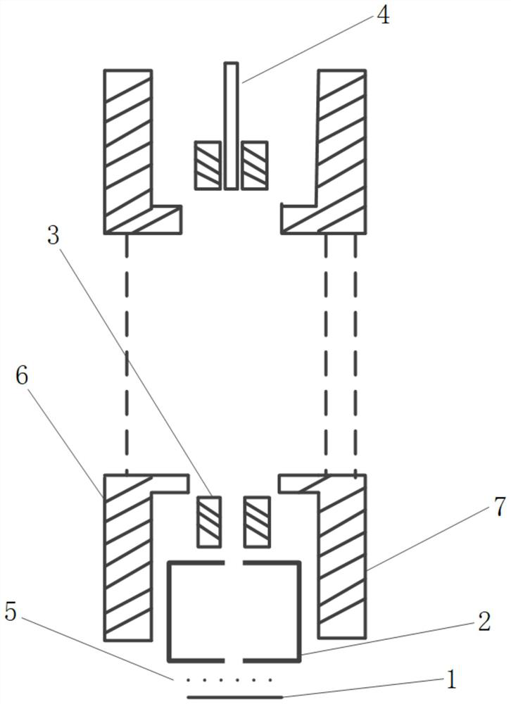
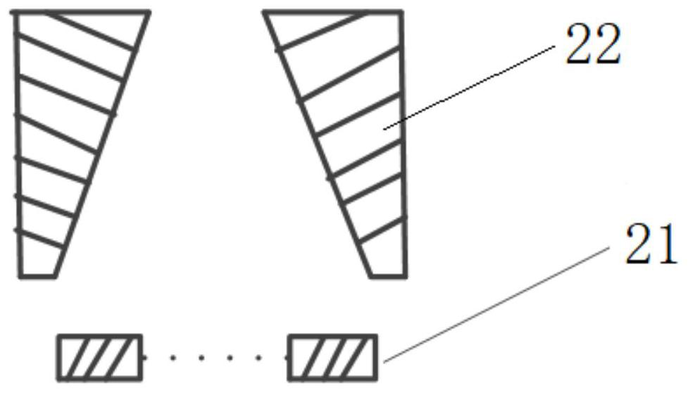
[0025] Such as Figure 2 to Figure 4 As shown, the storage ion source provided by this application includes a cathode 1, an electron focusing system 2, an ionization chamber 3 and an electron collector 4, wherein: the electron focusing system 2 is arranged above the cathode 1, and the electrons generated by the cathode 1 pass through the electron The ...


PUM


Abstract

The invention relates to the technical field of vacuum electronics, in particular to a storage type ion source, which comprises a cathode, an electron focusing system, an ionization chamber and an electron collector; the electron focusing system is arranged above the cathode, and electrons generated by the cathode form an electron beam current through the electron focusing system; the ionization chamber is arranged between the electron focusing system and the electron collector, grid meshes are arranged on the two sides of the ionization chamber, and a uniform electric field is formed betweenthe ionization chamber and the grid meshes; the electron beam current is ionized by the uniform electric field and then is received by the electron collector. Ions are trapped and stored by utilizingthe space charge effect of electrons, so that the initial states of the ions have good consistency, and the stability and uniformity of an ion beam are greatly improved when an ion source is led out.

Description

technical field [0001] The present application relates to the technical field of vacuum electronics, in particular, to a storage type ion source. Background technique [0002] Ion sources are widely used in mass spectrometers, surface coatings, ion thrusters and other fields. Improving the stability and uniformity of ion beams has become an important trend in technology development. For example, for time-of-flight mass spectrometers, ion energy and spatial uniformity are directly Affects performance parameters such as instrument resolution and sensitivity. [0003] There are many types of ion sources. Traditional electron collision ion sources are usually used in the ionization of gas molecules. The energy of electrons usually reaches about 70eV. The ions generated by ionization are evenly distributed in the entire ionization space. When the introduction voltage is applied or the repulsion voltage is increased, the ions are pulled out of the ionization chamber to form an io...

Claims


Application Information

Patent Timeline
Patent Type & Authority Applications(China)
IPC IPC(8): H01J27/02H01J49/10
CPCH01J27/022H01J27/024H01J49/10
Inventor 张虎忠李得天成永军习振华裴晓强董猛侯颖杰魏建平范栋陈会颖郭睿
Owner LANZHOU INST OF PHYSICS CHINESE ACADEMY OF SPACE TECH
Learn More