Direct-coupled magnetic suspension fan
A magnetic levitation and direct-connection technology, which is applied in the direction of electromechanical devices, mechanical equipment, and control of mechanical energy, can solve the problems of low speed, small pressure ratio, and low efficiency of the prime mover motor, and achieve long life of the fan, small starting current, and fewer components. Effect
- Summary
- Abstract
- Description
- Claims
- Application Information
AI Technical Summary
Problems solved by technology
Method used
Image

Examples
Embodiment 1
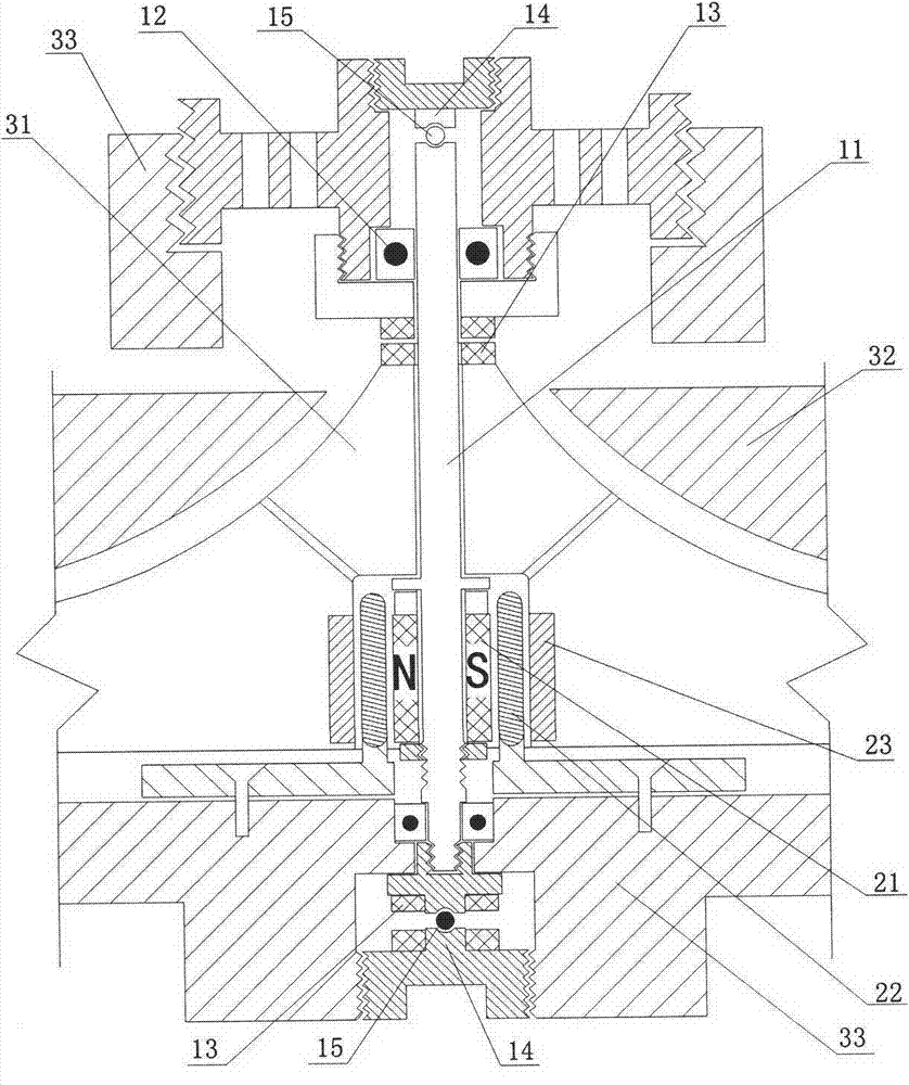
[0029] Embodiment 1 The permanent magnet rotor is axially distributed, and this embodiment is arranged vertically.
[0030] see figure 1 , the permanent magnet rotor 21 and the stator coil 22 are distributed in the axial direction, the permanent magnets of the permanent magnet rotor are arranged around the shaft according to the axial direction of the shaft, and the stator coils corresponding to the permanent magnet rotor are also arranged around the shaft according to the axial direction of the shaft. , that is, the permanent magnet rotor and the stator coil are both cylindrical; an armature 23 is provided on the other side of the stator coil corresponding to the permanent magnet rotor, or another permanent magnet rotor, and the armature or another permanent magnet rotor passes through the impeller. The body is fixedly connected with the shaft; the permanent magnet rotor 21 , the stator coil 22 and the armature 23 are placed in the cavity of the impeller 31 body. The impelle...
Embodiment 2
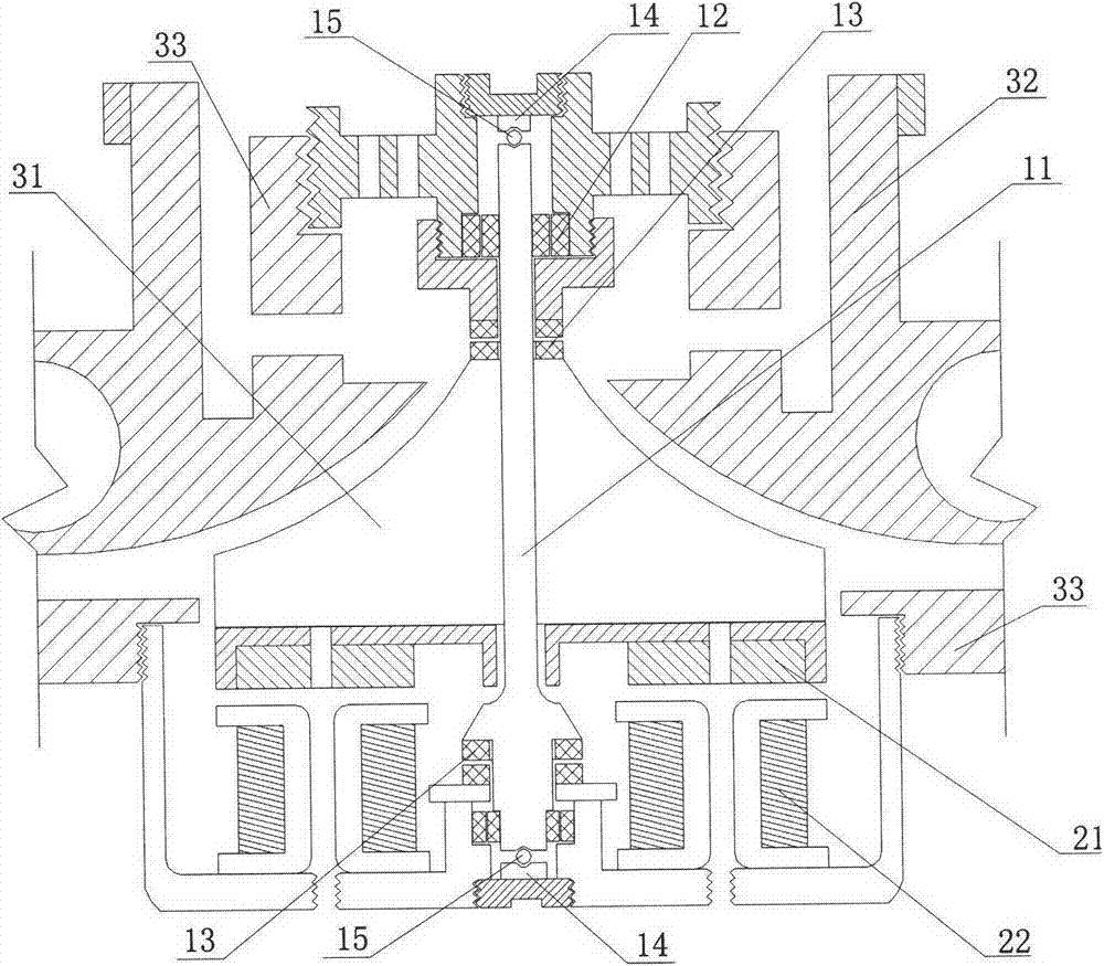
[0035] Embodiment 2 The permanent magnet rotor is radially distributed, and this embodiment is arranged vertically.
[0036] see figure 2 , the basic structure is similar to the embodiment 1, the special point is: the bearing adopts a magnetic suspension bearing, the magnetic suspension bearing is composed of an inner magnetic cylinder and an outer magnetic cylinder, the inner magnetic cylinder is fixedly installed on the shaft, and the outer magnetic cylinder is sleeved outside the inner magnetic cylinder and It is fixedly installed on the bracket, the inner diameter of the outer magnetic cylinder is larger than the outer diameter of the inner magnetic cylinder, and the adjacent surfaces of the inner magnetic cylinder and the outer magnetic cylinder are of the same polarity; The permanent magnet rotors are arranged according to the radial distribution of the shaft, and the corresponding stator coils are also arranged around the shaft according to the radial direction of the ...
Embodiment 3
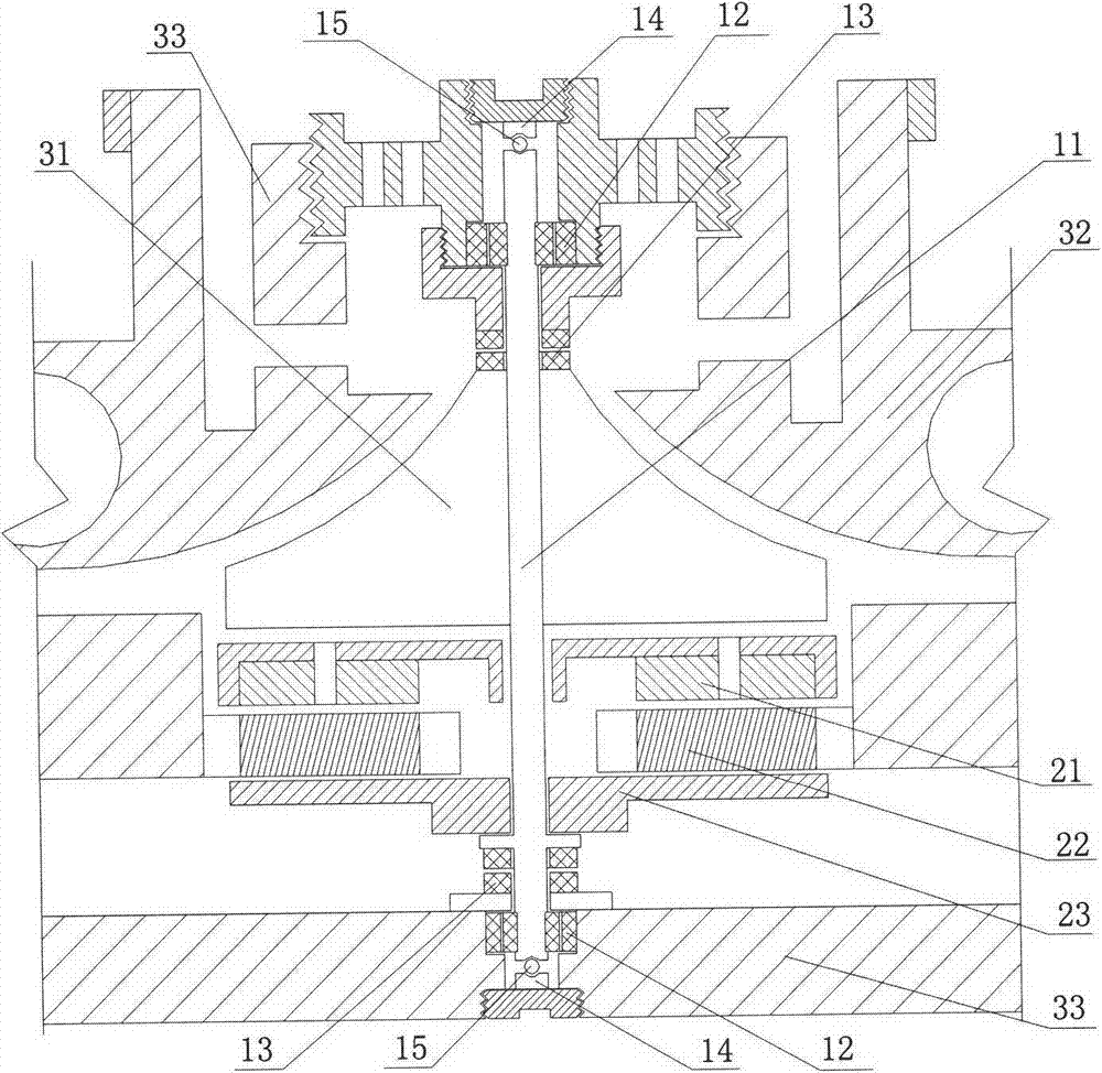
[0041] see image 3 , the basic structure is similar to that of Embodiment 2, the special feature is that the stator coil is also in the shape of a flat disc, and an armature 23 is arranged on the other side of the stator coil corresponding to the permanent magnet rotor, and the armature is fixedly connected to the shaft.
[0042] The stator coil is also in the shape of a flat disk, so as to increase the torque and reduce the axial distance, so that the shafting works in a rigid state, reduces the critical effect, and increases the torque.
[0043] The experimental results show that the speed can reach more than 30000rpm. The air pressure ratio can reach more than 2.
PUM
 Abstract
Description
Claims
Application Information
 - R&D Engineer
- R&D Manager
- IP Professional
- Industry Leading Data Capabilities
- Powerful AI technology
- Patent DNA Extraction
Browse by: Latest US Patents, China's latest patents, Technical Efficacy Thesaurus, Application Domain, Technology Topic.
© 2024 PatSnap. All rights reserved.Legal|Privacy policy|Modern Slavery Act Transparency Statement|Sitemap