Toothing for operation at a deflection angle and production method

A technology of deflection angle and tooth section, which is applied to the driving device of metal rolling mills, manufacturing tools, metal rolling, etc., and can solve the problems of not meeting the requirements of torque transmission, wear, and inability to transmit torque.

Active Publication Date: 2014-07-23
SMS GRP GMBH
View PDF7 Cites 3 Cited by
  • Summary
  • Abstract
  • Description
  • Claims
  • Application Information

AI Technical Summary

Problems solved by technology

If the torque to be transmitted is to be increased, the diameter of the work rolls has hitherto been increased, which leads especially to energy losses
Furthermore, in this case the mill stand also has to be designed more strongly
[0003] So far, the systems, for example, have cardan joints, which are located between the drive spindle and the roll, but do not meet the requirements of increased torque transmission
[0004] If the drive spindle is arranged at an angle to the rolls by means of spline toothing, the drive spindle can be designed to transmit higher rolling torques, but conventional toothing in drive spindles This results in edge loading, which ultimately results in very high wear and, as usual, the transmission of the desired high moments cannot be achieved.

Method used


Image

  • Toothing for operation at a deflection angle and production method
  • Toothing for operation at a deflection angle and production method
  • Toothing for operation at a deflection angle and production method

Examples


Embodiment Construction

[0038] First of all, it should be noted that concepts such as pitch circle, addendum circle, dedendum circle, generatrix, tooth line, mesh angle, deflection and others are generally known to experts and are therefore used without further elaboration in the instructions below.

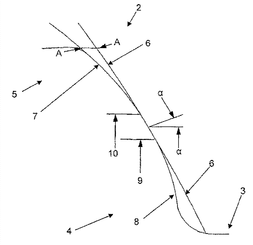
[0039] figure 1 A schematic cross section through the flank of a tooth 2 of the toothing 1 is shown. The tooth line runs in a convexly curved manner, so in principle it can also be called a curved tooth. To the right of this tooth flank there is a backlash 3 . The axis of rotation of the toothing 1 is perpendicular to the cross-sectional plane shown. The engagement angle α of the toothing can have different values, it can particularly preferably assume a value between 26° and 34°. The line 6 represents the contour of the tooth 2 in the form of a conventional involute 6 of the known involute toothing. According to the invention, however, the dedendum 4 and / or also the tooth tip 5 of the tooth 2 can ...


PUM


Abstract

The invention relates to a toothing (1), in particular of a drive spindle for driving a roll (13) in rolling mills or continuous casting plants, which comprises several teeth (2) and meshes with a second toothing in the manner of a spline, wherein a flank line (12) of the teeth (2) has a curvature and a deflection angle is formed between the rotational axis of the second toothing and the rotational axis of the toothing, wherein the toothing (1) is designed as having at least one of the following modifications: a tooth root relief of the teeth (2), and/or a tooth tip relief of the teeth (2), and/or a twist of the teeth (2).

Description

technical field [0001] The invention relates to the field of toothing, in particular of drive spindles for driving rolls in rolling mills or continuous casting plants. The invention relates to a toothing according to the preamble of claim 1 and to a production method for such a toothing. Background technique [0002] Certain applications require the transmission of force from the drive to the shaft at an angle. This requirement often arises, for example, in rolling mills. For example, if two work rolls are arranged one above the other, problems arise due to their relatively small diameter when it is desired to increase the torque to be transmitted. If the torque to be transmitted was to be increased, the diameter of the work rolls had hitherto been increased, which led, inter alia, to energy losses. Furthermore, the rolling stand also has to be designed more robustly in this case. [0003] Previous systems therefore had, for example, cardan joints, which were located bet...

Claims


Application Information

Patent Timeline
Patent Type & Authority Applications(China)
IPC IPC(8): B21B35/14F16D3/18
CPCB21B35/143F16D3/185Y10T403/7035Y10T29/49B21B35/14F16D3/18B23P15/00F16D1/02
Inventor J.默茨
Owner SMS GRP GMBH
Why Eureka
Try Eureka