Stamping part side wall curled rebounding control stamping device

A technology of stamping device and stamping parts, which is applied in the direction of manufacturing tools, metal processing equipment, forming tools, etc., can solve the problems of serious springback, difficult welding, assembly and other processes, scrap parts and other problems, so as to reduce stress difference and improve forming. Accuracy and quality, the effect of reducing sidewall curl and springback

Active Publication Date: 2014-07-30
SOUTH CHINA UNIV OF TECH
View PDF7 Cites 8 Cited by
  • Summary
  • Abstract
  • Description
  • Claims
  • Application Information

AI Technical Summary

Problems solved by technology

The performance is that after the forming is completed, the side wall that should have been straight is arc-shaped due to springback, which causes difficulties in subsequent welding, assembly and other processes, and even leads to the scrapping of parts
In addition, household appliances, kitchen utensils and other household products use a large number of stainless steel parts. Due to their large yield ratio, stainless steel parts have serious springback during processing and significant work hardening.
Common problems such as stainless steel washbasins, gas cooktops, and mechanical equipment shells are prone to curling of the side walls during the deep drawing process
[0003] The side wall curling phenomenon occurs in the side wall part, affected by the structure of the mold, the traditional springback compensation method is difficult to apply to the control of the side wall curling phenomenon

Method used


Image

  • Stamping part side wall curled rebounding control stamping device
  • Stamping part side wall curled rebounding control stamping device
  • Stamping part side wall curled rebounding control stamping device

Examples


Embodiment 1

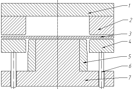
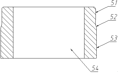
[0021] Such as figure 1 As shown, a stamping device for controlling the curling and springback of the side wall of a stamping part includes, from top to bottom, an upper die base 1, a die 2, a blank holder 4 that is driven and connected to an air ejector rod 6, and a convex ring that matches the die 2. Die 5, lower die base 7, the upper die base 1 is fixedly connected with the die 2 and moves synchronously, the punch 5 is fixedly connected with the lower die base 7, and the punch 5 includes the first stamping from top to bottom part 51 and the second stamping part 53, and the transition between the first stamping part 51 and the second stamping part 53 is smooth through the transition curve part 52, wherein the outer contour of the side wall of the first stamping part 51 is consistent with the concave die 2 The gap of the side wall is 1.2 times of the thickness of the plate to be punched, the gap between the outer contour of the side wall of the second stamping part 53 and the...

Embodiment 2

[0026] Such as figure 1 As shown, a stamping device for controlling the curling and springback of the side wall of a stamping part includes, from top to bottom, an upper die base 1, a die 2, a blank holder 4 that is driven and connected to an air ejector rod 6, and a convex ring that matches the die 2. Die 5, lower die base 7, the upper die base 1 is fixedly connected with the die 2 and moves synchronously, the punch 5 is fixedly connected with the lower die base 7, and the punch 5 includes the first stamping from top to bottom part 51 and the second stamping part 53, the transition between the first stamping part 51 and the second stamping part 53 is smooth through the transition curve part 52, wherein the outer contour of the side wall of the first stamping part 51 is consistent with the die 2 The gap of the side wall is 1.3 times of the thickness of the plate to be punched, the gap between the outer contour of the side wall of the second stamping part 53 and the side wall o...

Embodiment 3

[0031] Such as figure 1 As shown, a stamping device for controlling the curling and springback of the side wall of a stamping part includes, from top to bottom, an upper die base 1, a die 2, a blank holder 4 that is driven and connected to an air ejector rod 6, and a convex ring that matches the die 2. Die 5, lower die base 7, the upper die base 1 is fixedly connected with the die 2 and moves synchronously, the punch 5 is fixedly connected with the lower die base 7, and the punch 5 includes the first stamping from top to bottom part 51 and the second stamping part 53, the transition between the first stamping part 51 and the second stamping part 53 is smooth through the transition curve part 52, wherein the outer contour of the side wall of the first stamping part 51 is consistent with the die 2 The gap of the side wall is 1.6 times of the thickness of the plate to be punched, the gap between the outer contour of the side wall of the second stamping part 53 and the side wall o...


PUM


Abstract

The invention discloses a stamping part side wall curled rebounding control stamping device which comprises an upper die base, a concave die, a blank holder, a convex die and a lower die base from top to bottom, wherein the blank holder is in driving connection with a holder-on rod; the convex die is matched with the concave die; the upper die base is fixedly connected with the concave die and moves synchronously with the concave die; the convex die is fixedly connected with the lower die base; the convex die comprises a first stamping part and a second stamping part from top to bottom; the first stamping part and the second stamping part are in smooth transition by virtue of a transition curve part; a clearance between the outer contour of the side wall of the first stamping part and the side wall of the concave die is 1.2-1.6 times of the thickness of a to-be-stamped plate; a clearance between the outer contour of the side wall of the second stamping part and the side wall of the concave die 2 is 0.8-0.9 times of the thickness of the to-be-stamped plate; the projection length of the transition curve part in the stamping direction is 2-3 times of the thickness of the to-be-stamped plate. According to the stamping part side wall curled rebounding control stamping device, the die clearance is changed during a stamping process, so that the stress difference between inner and outer layers of a material is decreased, side wall curled rebounding of parts is effectively controlled, and the formation precision and quality of the parts are improved.

Description

technical field [0001] The invention relates to a stamping device for controlling the curling and springback of the side wall of a stamping part. By optimizing the structure of the punch, the mold gap of the key part of the part is changed with the stamping process, so as to achieve the purpose of controlling the curling springback of the side wall, and belongs to the technical field of stamping forming. Background technique [0002] Side wall curl is a defect that is prone to occur during the bending and drawing process of parts with flanges. It is a springback phenomenon and widely exists in the forming process of automotive beam parts, stainless steel deep drawing parts and other parts. The performance is that after the forming is completed, the side wall that should have been straight is arc-shaped due to springback, which causes difficulties in subsequent welding and assembly processes, and even leads to scrapping of parts. In addition, household appliances, kitchen ute...

Claims


Application Information

Patent Timeline
Patent Type & Authority Applications(China)
IPC IPC(8): B21D37/10B21D22/20
Inventor 周驰颜武军
Owner SOUTH CHINA UNIV OF TECH
Why Eureka
Try Eureka