Feeding mechanism of stamping equipment for motor rotor piece

A stamping equipment and motor rotor technology, applied in the field of stamping equipment, can solve problems such as difficult molds, stamping material jams, inaccurate material distribution, etc., and achieve the effects of simple and convenient maintenance, long service life and wide application range

Inactive Publication Date: 2014-07-30
池海平
View PDF7 Cites 16 Cited by
  • Summary
  • Abstract
  • Description
  • Claims
  • Application Information

AI Technical Summary

Problems solved by technology

Although the patented technology realizes automation and reduces labor intensity, there are still many defects. The step of sucking the blanks out from the silo can be called splitting. The blanks are fed into the mold at an angle. The above method has high requirements on the size, precision and cleanliness of the blanks. For example, there are oil stains on the surface of the blanks, which are easy to stick together. The material is not accurate, and the subsequent stamping may jam the material
In addition, the rotating handle is used to transfer the raw materials into the mold, and the rotating speed cannot be very high, otherwise it is easy to fly the material, or it is difficult to accurately fall into the mold, the scrap rate is high, the product quality is uneven, and the production efficiency needs to be improved.

Method used


Image

  • Feeding mechanism of stamping equipment for motor rotor piece
  • Feeding mechanism of stamping equipment for motor rotor piece
  • Feeding mechanism of stamping equipment for motor rotor piece

Examples


Embodiment Construction

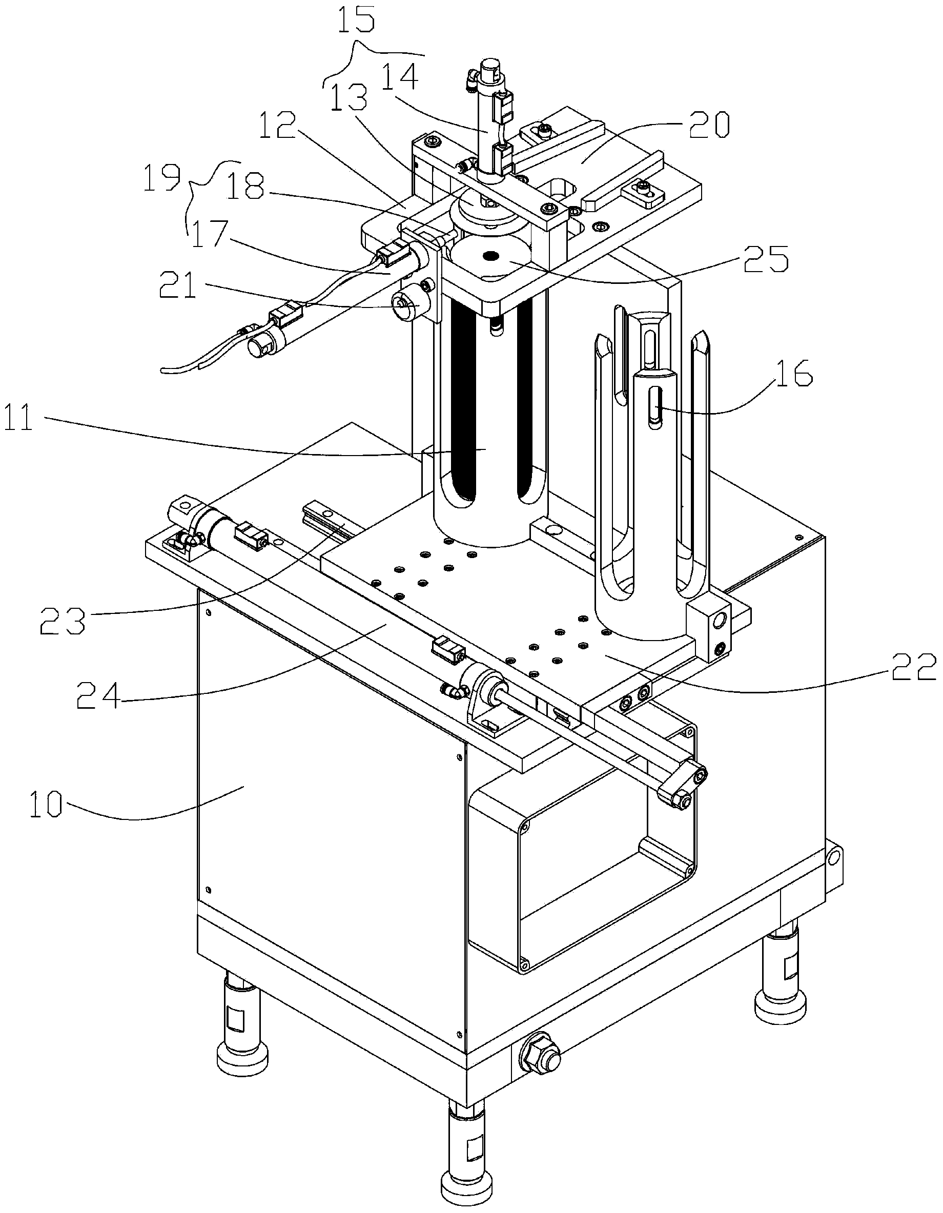
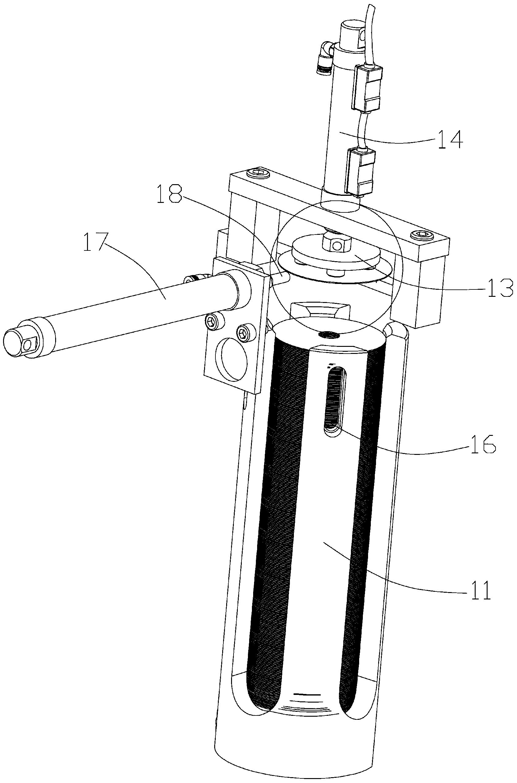
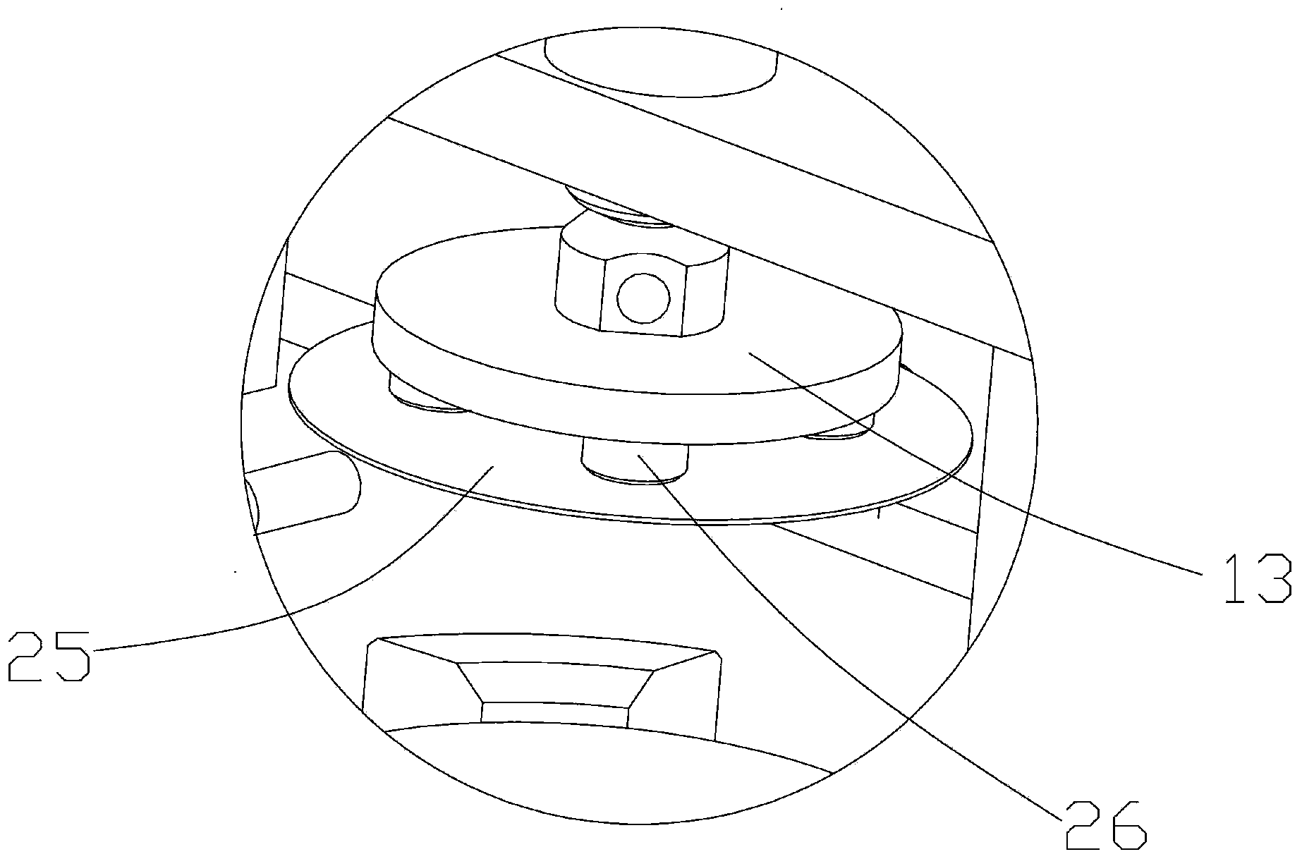
[0018] Below in conjunction with accompanying drawing, the present invention will be further described with specific embodiment, see figure 1 —3: The feeding mechanism of the stamping equipment for the motor rotor sheet, including a frame 10, the frame 10 is provided with a storage barrel 11 and a material distribution device 15, and the material distribution device 15 is arranged on the storage device through a support frame 12 Above the material storage tank 11, a material ejector rod is arranged below the material storage tank 11, and the material ejector rod penetrates from the bottom of the material storage tank 11 to push the blank 25 upward, wherein the material distribution device 15 includes a suction The material tray 13 and the power assembly 14 that drives the reciprocating linear movement of the material suction plate 13, the material suction plate 13 is located directly above the discharge port of the material storage barrel 11, and can quickly, conveniently and a...


PUM


Abstract

The invention particularly relates to a feeding mechanism of stamping equipment for a motor rotor piece, and belongs to the technical field of stamping equipment. The feeding mechanism comprises a frame, wherein a material storage bucket and a material distribution device are arranged on the frame; the material distribution device is arranged above the material storage bucket through a support frame, and comprises a material suction disk and a power component for driving the material suction disk to perform reciprocating straight line movement; a magnetic device is arranged at the discharge end of the material storage bucket; a push device is arranged on one side of the material suction disk; a material guide groove is formed in the other side, opposite to the push device, of the material suction disk. The feeding mechanism has low requirements on the size and the precision or the cleanliness of blank and has a wide application range, is simple in structure, low in manufacturing cost, simple and convenient to maintain, and long in service life; materials are distributed accurately, and one piece is distributed for each time; the phenomena of piece clamping and material blocking are avoided; the production efficiency is high; 90-95 pieces of blank can be machined per minute averagely when the feeding mechanism is matched with a stamping mechanism; manpower is saved; one person can control a plurality of machines.

Description

technical field [0001] The invention belongs to the technical field of stamping equipment, and relates to equipment for stamping motor rotor slices, in particular to a feeding mechanism of the stamping equipment for motor rotor slices. Background technique [0002] The use of punching machines to produce motor rotor pieces is the most conventional and most effective production method. Most companies still use manual feeding, which is labor-intensive and low in production efficiency. One person can only operate one punching machine, and the labor cost is high. And There is also great danger in the feeding process. The patent with the authorized announcement number CN201493405U discloses a main body mechanism for stamping and feeding motor stator and rotor sheet materials. Quickly retract, and at the same time, the feeding handle rotates horizontally clockwise from the reset position. When it is close to the feeding mechanism, because the suction force of the suction contact ...

Claims


Application Information

Patent Timeline
Patent Type & Authority Applications(China)
IPC IPC(8): B21D43/02B21D43/18
Inventor 池海平
Owner 池海平
Why Eureka
Try Eureka