Self-cooling center driller or self-cooling countersink driller

A self-cooling and countersinking technology, which is applied in center drilling, drilling/drilling equipment, drilling repair, etc., can solve the problems of insufficient cooling effect, single main cutting edge, and reduced hardness of the cutter head, so as to save resources , Improve efficiency and reduce tool hardness

Inactive Publication Date: 2014-07-30
李仕清
View PDF9 Cites 2 Cited by
  • Summary
  • Abstract
  • Description
  • Claims
  • Application Information

AI Technical Summary

Problems solved by technology

[0002] At present, the main cutting edge of the center drill or countersink used in mechanical processing is roughly a single structure, which is extremely undurable, especially when drilling and milling workpieces with high hardness, a large amount of heat is generated, resulting in a de...

Method used


Image

  • Self-cooling center driller or self-cooling countersink driller
  • Self-cooling center driller or self-cooling countersink driller
  • Self-cooling center driller or self-cooling countersink driller

Examples


Embodiment approach 1

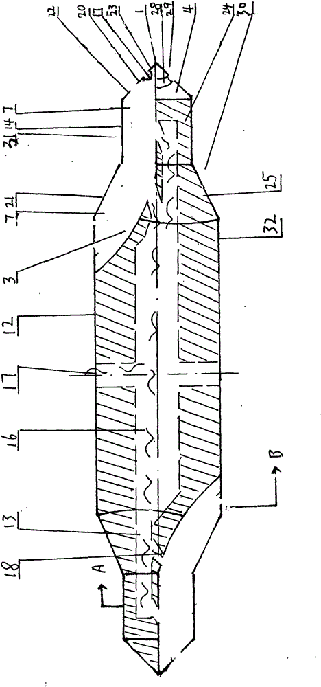
[0028] Such as figure 1 , Figure 20-Figure 23 As shown, the self-cooling center drill or the self-cooling countersink drill on the center drill without cone guard in the first embodiment of the present invention mainly relates to a center drill or a counter drill used for machining, including a tool head 1 , The tool head 1 is integrally provided with a front cutting cone 29 and a rear cutting cone 30, the front cutting cone 29 and the rear cutting cone 30 are integrally provided with a front cutter body 31, and the rear part of the rear cutting cone 30 is a rear cutter body 32. The front cutting cone 29, the front cutter body and the rear cutting cone 30 are respectively composed of a plurality of integral cutting inserts or cutting insert bodies 2, and each cutting insert or cutting insert body 2 is formed by an edge facing the outer side of the cutting direction Is the minor cutting edge 14, the surface facing the direction of rotation where the minor cutting edge 14 is loca...

Embodiment approach 2

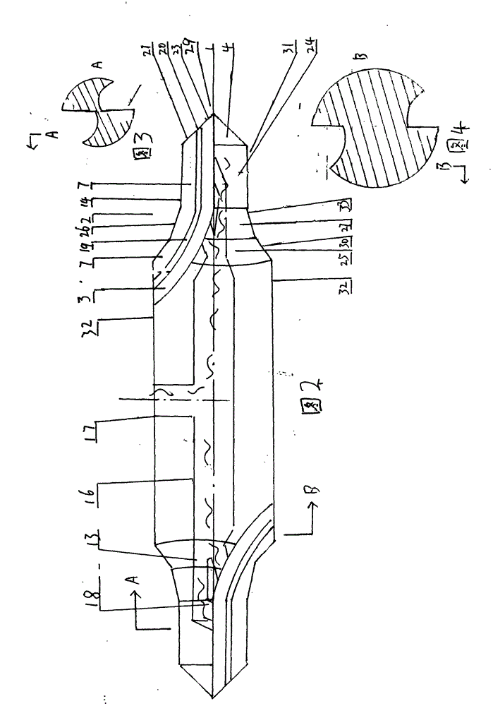
[0032] Such as figure 2 , image 3 , figure 2 , Figure 20-Figure 23 As shown, the self-cooling center drill or the self-cooling countersink drill example of the second embodiment of the present invention is based on the first embodiment. In this embodiment, a notch edge 20 is provided on the main cutting edge 21. The cutting edge 20 extends to the cutting surface 7 to form a groove 19, and the arrangement of the notch cutting edge 20 is applied to a center drill with a guard cone. Compared with the first embodiment, the cutting efficiency can be greatly improved.

Embodiment approach 3

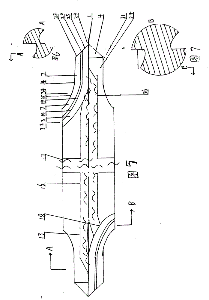
[0034] Such as image 3 , Figure 4 Figure 7 , Figure 20-Figure 23 As shown, the self-cooling center drill or the self-cooling countersink drill example of the third embodiment of the present invention is based on the first and second embodiments. This embodiment applies the above-mentioned technology to the arc center drill , The implementation effect is the same as that of the first embodiment.


PUM


Abstract

The invention provides a self-cooling center driller or self-cooling countersink driller and mainly relates to a center driller or countersink driller used for machining. The self-cooling center driller or self-cooling countersink driller is characterized in that each spiral bar of the center driller or countersink driller is provided with a cutting blade; a cutting surface is formed along the outer side of the cutting blade; the cutting surface is formed on the front part of the cutting blade facing to a cutting direction; cooling holes or cooling slots are arranged at the axial center and the positions, close to the center of the center driller or countersink driller; the lower ends of the cooling holes or cooling slots are communicated with cooling openings arranged in the grooves on the front part of the cutting surface of the center driller or countersink driller; the upper end of the center driller or countersink driller is communicated with an integrally arranged cooling pipe of a shank of the center driller or countersink driller; a connecting port is arranged on a shank body of the shank or at the front end at the axial center of the shank of the center driller or countersink driller.

Description

Technical field: [0001] The invention relates to a self-cooling center drill or a self-cooling countersink, which is used in drilling machine processing and fitter maintenance. Background technique: [0002] At present, the main cutting edge of the center drill or countersink used in mechanical processing is roughly a single structure, which is extremely undurable, especially when drilling and milling workpieces with high hardness, a large amount of heat is generated, resulting in a decrease in the hardness of the cutter head, resulting in The wear and tear of the head, the cooling technology has become the bottleneck of the tool use. It is difficult to inject the coolant directly into the cutting part with ordinary technology, and the ideal cooling effect cannot be achieved. Invention content: [0003] The present invention is proposed in view of the above problems, and aims to provide a self-cooling center drill or a self-cooling countersink, which has high cooling effic...

Claims


Application Information

Patent Timeline
IPC IPC(8): B23B51/06
CPCB23B51/0063B23B51/06B23B51/10
Inventor 李仕清
Owner 李仕清
Why Eureka
Try Eureka