Truck braking radiating system
A brake system and technology for trucks, applied in vehicle parts, brakes, transportation and packaging, etc., can solve the problems of drivers wasting time and money, increasing fuel consumption, increasing the weight of trucks, etc., and achieve good heat dissipation effect
- Summary
- Abstract
- Description
- Claims
- Application Information
AI Technical Summary
Problems solved by technology
Method used
Image
Examples
Embodiment 1
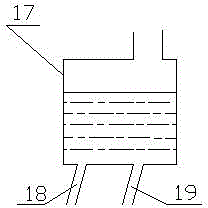
[0043] image 3 It is a schematic diagram of the structure of the water tank circulating cooling device in this embodiment. The water tank circulating cooling device includes a water tank 17, a water tank inlet pipe 18 and a water tank outlet pipe 19. The water tank 17 is located at a position higher than the girder of the truck. Water pipe 18 and water tank outlet pipe 19;
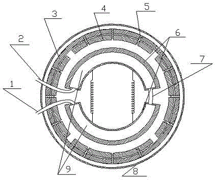
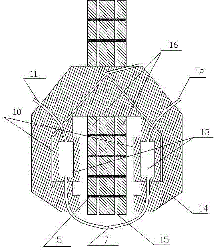
[0044] When the driver steps on the brakes, the brake shoe 6 contacts and rubs against the brake pad 4 on the inner wall of the brake drum 3, and the heat energy generated by the friction makes the temperature of the water in the brake shoe inner cavity 9 rise, and the water that has increased in temperature becomes steam from After the brake shoe outlet pipe 2 and the water tank inlet pipe 18 flow into the water tank, they are cooled by the water in the water tank 17, and then flow out from the water tank outlet pipe 19, and the evaporated water flows into the brake shoe inner chamber 9 through the brake...
Embodiment 2
[0046] Figure 4 As shown, it is a structural schematic diagram of a mechanical circulation cooling device in this embodiment, including a generator 27, a cable 28, a motor 22, a high-pressure pipe 30, a return pipe 20 and a connected water pump 29 and a radiator 21, and the generator 27 is provided by a truck The drive shaft 23 of the drive shaft 23 drives its operation through the splitter 24 and the output drive shaft 26, the output end of the generator 27 is connected with the motor 22 through the cable 28, and one end of the motor 22 is connected with the fan blade of the water pump 29 and the radiator 21, thereby driving Connected water pump 29 and radiator 21, the other end of water pump 29 is connected with one end of high pressure pipe 30, the other end of high pressure pipe 30 is connected with brake shoe inlet pipe 1, the other end of radiator 21 is connected with one end of return pipe 20, The other end of the return pipe 20 is connected with the brake shoe outlet ...
Embodiment 3
[0050] Figure 5 As shown, it is a schematic diagram of the structure of the mechanical circulation cooling device in this embodiment, including the high-pressure pipe 30, the return pipe 20, the connected water pump 29 and the radiator 21, and the water pump 29 and the radiator 21 are passed through the clutch by the transmission shaft 23 of the truck 24 and the output drive shaft 26 drive the operation, one end of the water pump 29 is connected with one end of the high pressure pipe 30, the other end of the high pressure pipe 30 is connected with the brake shoe inlet pipe 1, one end of the radiator 21 is connected with one end of the return pipe 20, and the return pipe The other end of 20 links to each other with brake shoe outlet pipe 2.
[0051] In order to utilize the power of transmission shaft 23 rationally, the tail end of gearbox 25 is connected with transmission shaft 23, and transmission shaft 23 is set to be connected with one end of splitter 24, and the other end ...
PUM
 Abstract
Description
Claims
Application Information
 - R&D
- Intellectual Property
- Life Sciences
- Materials
- Tech Scout
- Unparalleled Data Quality
- Higher Quality Content
- 60% Fewer Hallucinations
Browse by: Latest US Patents, China's latest patents, Technical Efficacy Thesaurus, Application Domain, Technology Topic, Popular Technical Reports.
© 2025 PatSnap. All rights reserved.Legal|Privacy policy|Modern Slavery Act Transparency Statement|Sitemap|About US| Contact US: help@patsnap.com


