Rotary calcination device and rotary calcination process

A technology of rotary roasting and rotary devices, which is applied in the direction of rotary drum furnaces, furnaces, lighting and heating equipment, etc., can solve the problems of unfavorable reactions and purification of roasted products, unstable product quality, low equipment operation rate, etc., and achieve increased tail gas treatment The effect of reducing the energy consumption of equipment operation and heating evenly

Active Publication Date: 2014-07-30
SHANDONG TIANLI DRYING TECH & EQUIP
View PDF6 Cites 0 Cited by
  • Summary
  • Abstract
  • Description
  • Claims
  • Application Information

AI Technical Summary

Problems solved by technology

[0004] However, most of the current rotary roasting kilns have the following problems at a temperature of 0-600 °C: some do not add a copying board, the material moves at the bottom of the kiln, the heating surface is limited and the heating is uneven; the heating medium (flue gas, etc.) and the material Direct contact will bring secondary pollution to the material, which is not conducive to the purification of the reaction and roasted products, and at the same time increases the amount of exhaust gas; in the rotary kiln equipped with heating tubes, the tubes are generally fixed on the kiln wall and rotate together with the kiln, and the distribution Filling most of the space in the kiln increases the difficulty of sealing, resulting in a complex sealing structure, and when individual tubes break, the kiln must be stopped to deal with it, which is not conducive to daily maintenance and increases costs, etc.
[0005] The existence of these problems has led to unstable product quality, low equipment operation rate, high energy consumption and high cost

Method used


Image

  • Rotary calcination device and rotary calcination process
  • Rotary calcination device and rotary calcination process

Examples


Embodiment Construction

[0031] The present invention will be further described below in conjunction with the accompanying drawings and embodiments.

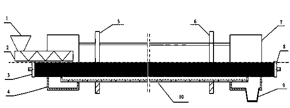
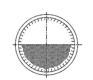
[0032] figure 1 Among them, the silo 1 and the feeder 2 are connected to form a conveying device, the sealing devices Ⅰ4 and Ⅱ7 are connected with the rotary drum 10, and the two ends of the rotary drum 10 are equipped with a sealing device Ⅰ4 and a sealing device Ⅱ7, and the sealing device is connected to a static heat soaking device Ⅰ3 , Soaking device Ⅱ8, soaking device Ⅰ3, and Ⅱ8 are connected by heating tubes, and the tubes run through the entire kiln body. No tubes are installed in the upper part of the kiln, and the inner wall of the kiln is equipped with lifting plates. The conveying device is composed of a silo 1 and a feeder 2, and the material in the silo 1 enters the kiln for roasting through the feeder 2. Sealing device Ⅰ4 and sealing device Ⅱ7 are shaft end contact seals. The rotary part is a rotary cylinder 10, the front roller 5 and th...


PUM


Abstract

The invention discloses a rotary calcination device and a rotary calcination process. The rotary calcination device comprises static state soaking devices, heating tubes, sealing devices, a rotating device, and a conveying device, wherein the sealing devices are arranged at the two ends of the rotating device, the conveying device used for conveying materials passes through the sealing devices and conveys the materials to the rotating device, the static state soaking device is arranged on the outer side of each sealing device, the two static state soaking devices are connected through the heating tubes axially penetrating through the rotating device, the heating tubes are arranged at the lower half part of the rotating device and are separately fixed, and the heating tubes do not rotate along with a kiln body. The heating tubes are only distributed at the lower half part of the interior of a kiln and occupy 40%-60% of the space of the kiln, and only about half of the heating tubes are distributed in the kiln, so that the material is saved, the handling capacity is hardly affected, and the equipment investment cost is greatly lowered.

Description

[0001] technical field [0002] The invention relates to a rotary roasting device and a process, in particular to a device and a process of a medium-low temperature rotary roasting kiln. Background technique [0003] The medium and low temperature rotary roasting kiln can be adapted to the roasting of various industrial raw materials because of its good mixing performance and efficient heat transfer capacity. [0004] However, most of the current rotary roasting kilns have the following problems at a temperature of 0-600 °C: some do not add a copying board, the material moves at the bottom of the kiln, the heating surface is limited and the heating is uneven; the heating medium (flue gas, etc.) and the material Direct contact will bring secondary pollution to the material, which is not conducive to the purification of the reaction and roasted products, and at the same time increases the amount of exhaust gas; in the rotary kiln equipped with heating tubes, the tubes are ...

Claims


Application Information

Patent Timeline
Patent Type & Authority Applications(China)
IPC IPC(8): F27B7/10F27B7/20F27B7/34
Inventor 李选友王成运赵改菊尹凤交
Owner SHANDONG TIANLI DRYING TECH & EQUIP
Why Eureka
Try Eureka