Front frame positioner

A technology of positioner and front frame, which is applied in the direction of auxiliary devices, auxiliary welding equipment, welding/cutting auxiliary equipment, etc., can solve the problems of repeated welding of weld seams, repeated welding of weld seams, and unstable rotation of motors, etc., to achieve The effect of reducing end jump and eccentricity, improving welding quality and ensuring stability

Inactive Publication Date: 2015-12-30
CHENGDU HAILINGDA MACHINERY
View PDF7 Cites 0 Cited by
  • Summary
  • Abstract
  • Description
  • Claims
  • Application Information

AI Technical Summary

Problems solved by technology

The positioner can make the weld seam on the workpiece be welded in the ideal boat-shaped position or flat welding position, which improves the welding efficiency and reduces the labor intensity; however, in the actual operation process, the weld seam is often Repeated welding or missing welding occurs. The reason is that under the long-term working load, the rotation of the motor is often unstable, sometimes fast and sometimes slow. Whether it is manual welding or mechanical intelligent welding, the solder joints are easy to gather together or the intervals are very small. A long distance, which will cause repeated welding or missing welding of the weld seam

Method used


Image

  • Front frame positioner
  • Front frame positioner
  • Front frame positioner

Examples


Embodiment 1

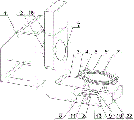
[0023] Such as Figure 1 to Figure 3 As shown, the front frame positioner of the present invention includes a mounting base 1, a motor 2 and an L-shaped support arm 3 are arranged inside the mounting base 1, and a through hole is opened on the vertical part of the L-shaped support arm 3. The output shaft of the motor 2 passes through the through hole and is connected with the L-shaped support arm 3. A DC motor 8 is fixedly installed on the horizontal portion of the L-shaped support arm 3. The output end of the DC motor 8 is connected with a turntable 7. On the turntable 7 is provided with a plurality of internal thread grooves 6, the internal thread groove 6 is an annular body composed of a plurality of adjacent through holes, the internal thread groove 6 radially radiates along the center of the turntable 7; it also includes a pressure plate 5, the The pressure plate 5 is connected to the internal thread groove 6 through the bolt 4, and a shock absorbing structure 17 is arran...

Embodiment 2

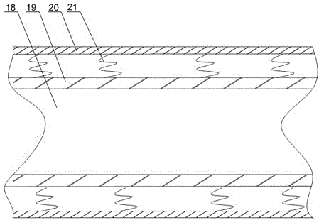
[0025] Such as figure 1 with image 3 As shown, this embodiment is based on Embodiment 1, the shock absorbing structure 17 includes a sleeve 20, a bearing 19 is installed in the sleeve 20, and a plurality of springs are installed between the outer wall of the bearing 19 and the inner wall of the sleeve 20 21, and the spring 21 is in a compressed state. The output end 18 of the motor passes through the bearing 19 to ensure that the L-shaped support arm 3 can freely rotate 360 ​​degrees in the vertical direction. A plurality of springs 21 are installed between the outer wall of the bearing 19 and the inner wall of the sleeve 20, and the springs 21 are always in a compressed state. When the output terminal 18 of the motor runs out radially, the elastic force generated by the spring 21 is opposite to the direction of the radial stress, which can offset the radial stress. Also comprise rotating shaft 9, one end of described rotating shaft 9 is connected with rotating disk 7 botto...

Embodiment 3

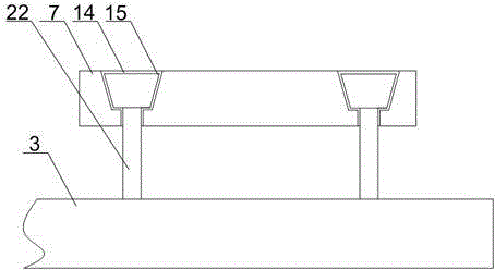
[0027] Such as figure 1 with figure 2As shown, in this embodiment, on the basis of Embodiment 1, an annular trapezoidal groove 14 is provided at the bottom of the turntable 7, a support rod 22 is installed on the horizontal part of the L-shaped support arm 3, and the end of the support rod 22 A protrusion 15 is fixedly connected, and the protrusion 15 engages with the annular trapezoidal groove 14; a balance weight 16 is installed on the upper end of the vertical part of the L-shaped support arm 3 . The bottom of the rotating disk 7 is provided with an annular trapezoidal groove 14, and the protrusion 15 on the support rod 22 is engaged with the annular trapezoidal groove 14. When the L-shaped support arm 3 rotates in the vertical direction, the front frame of the car is inverted, and the front frame itself The gravity will pull the output shaft of the motor 2, which not only increases the operating load of the motor 2, but also causes some damage to the motor 2. The support...


PUM


Abstract

The invention discloses a front frame position changing machine which comprises a mounting seat. A motor and an L-shaped supporting arm are arranged in the mounting seat, and a through hole is formed in the vertical part of the L-shaped supporting arm. An output shaft of the motor penetrates through the through hole to be connected with the L-shaped supporting arm, and a DC motor is fixedly mounted on the horizontal part of the L-shaped supporting arm. A rotating table is connected to the output end of the DC motor, a plurality of internal threaded grooves are formed in the rotating table, the internal threaded grooves are annular bodies which are formed by a plurality of adjacent through holes, and the internal threaded grooves radiate in the radial direction along the circle center of the rotating table. The front frame position changing machine further comprises pressing plates, the pressing plates are connected with the internal threaded grooves through bolts, and a damping structure is arranged on the through hole. When the motor drives the L-shaped supporting arm to rotate, radial run-out can happen to the output shaft of the motor, so that the L-shaped supporting arm moves up and down. The damping structure is mounted on the through hole, the output end of the motor penetrates through the damping structure so that the radial run-out influence can be removed, the stability of a front frame in the welding process can be further guaranteed, and the welding quality of the front frame is improved.

Description

technical field [0001] The invention relates to a welding auxiliary tool, in particular to a front frame positioner. Background technique [0002] Welding technology has been widely used in light and heavy industries such as aviation and aerospace. The quality of welding directly affects the quality of products and the performance of the whole machine. Therefore, improving welding technology and improving welding quality play an important role in industrial modernization. Among them, improving the level of welding mechanization and automation and realizing the modernization of welding technology and equipment are an important aspect of improving welding quality. Generally speaking, in welding production, there will be When encountering welding displacement and selecting a suitable welding position, in response to this actual need, there are many positioners on the market, which can rotate the various welds of the workpiece to be welded to the best position, thereby avoiding ...

Claims


Application Information

Patent Timeline
Patent Type & Authority Patents(China)
IPC IPC(8): B23K37/047
CPCB23K37/047
Inventor 陈志强
Owner CHENGDU HAILINGDA MACHINERY
Why Eureka
Try Eureka