
A hot blast stove exhaust air recovery device with an exhaust air buffer tank

A recovery device and hot blast stove technology, applied in the field of hot blast stoves in the metallurgical industry, can solve the problems of simplicity and failure to recycle under pressure, and achieve the effects of reducing noise and reducing peaks

Active Publication Date: 2015-08-05
BEIJING SHOUGANG INT ENG TECH
View PDF5 Cites 0 Cited by
  • Summary
  • Abstract
  • Description
  • Claims
  • Application Information

AI Technical Summary

Problems solved by technology

[0008] The purpose of the present invention is to provide a hot blast stove exhaust air recovery device with an exhaust air buffer tank, which solves the problem that the current exhaust air recovery system is too simple, so in fact the exhaust air of the current hot blast stove is directly discharged into the atmosphere, which cannot Recycle its pressure energy

Method used


Image

  • A hot blast stove exhaust air recovery device with an exhaust air buffer tank
  • A hot blast stove exhaust air recovery device with an exhaust air buffer tank
  • A hot blast stove exhaust air recovery device with an exhaust air buffer tank

Examples


Embodiment Construction

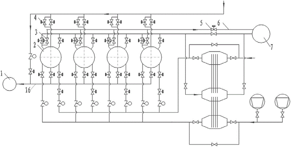
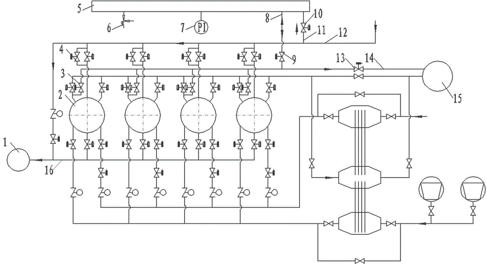
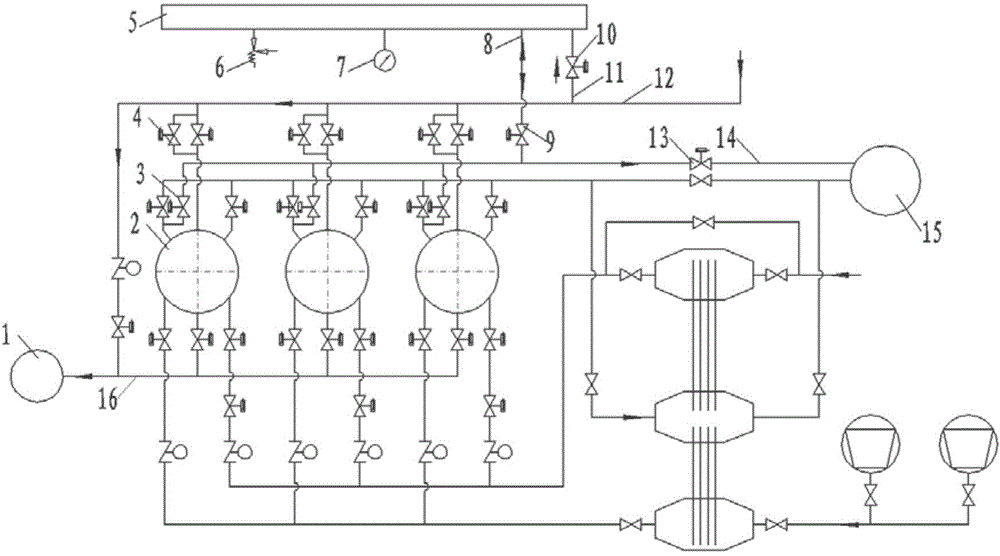
[0029] The present invention includes: blast furnace 1, hot blast stove 2, waste air valve 3, cold air equalizing valve 4, waste air buffer tank 5, safety valve 6, pressure gauge 7, waste air connecting pipe 8, waste air connecting pipe control valve 9, Cold air equalizing slow filling valve 10, slow equalizing connecting pipe 11, cold air pipe 12, waste air main control valve 13, waste air main 14, hot blast stove chimney 15, hot air pipe 16.

[0030] image 3 It is a concrete implementation of the present invention (taking 3 hot blast stoves as an example).

[0031] The waste air ducts of the three hot blast stoves merge into a waste wind main pipe 14, which is connected to the hot blast stove chimney 15, and a waste wind main control valve 13 is arranged on the waste wind main pipe. A waste air buffer tank 5 is set in the system, its working pressure is equal to the cold air pressure, and its working temperature is the highest temperature of the hot blast stove waste air. ...


PUM


Abstract

The invention discloses a waste air recycling device of a hot blast stove with a waste air buffer tank, and belongs to the technical field of the hot blast stove in the metallurgical industry. The waste air recycling device comprises a blast furnace, a hot blast stove, a waste air valve, a cold air pressure-equalizing valve, a waste air buffer tank, a safety valve, a pressure meter, a waste air communicating tube, a waste air communicating tube control valve, a cold air pressure-equalizing slow charging valve, a slow pressure-equalizing communicating tube, a cold air pipeline, a waste air header tube control valve, a waste air header tube, a hot blast stove chimney and a hot air pipeline, wherein a blast furnace air blower is connected with the hot blast stove (2) by a cold air pipeline (12); the hot blast stove (2) and the blast furnace (1) are connected by the hot air pipeline (16); the cold air pressure-equalizing valve (4) is arranged on a pressure-equalizing pipeline of each hot blast stove; the waste air valve (3) is arranged on the waste air pipeline of each hot blast stove; the waste air buffer tank (5) is arranged near the hot blast stove; the waste air communicating tube (8) is arranged for connecting the waste air header tube (14) with the waste air buffer tank (5). The waste air recycling device disclosed by the invention has the advantages that furnace condition fluctuation, which is brought by pressure-equalizing operation of the hot blast stove, of the blast furnace can be relieved; and requirements of the blast furnace air blower on air charging capacity are further lowered due to buffer effect.

Description

technical field [0001] The invention belongs to the technical field of hot blast stoves in the metallurgical industry, and in particular provides a hot blast stove waste air recovery device with a waste wind buffer tank; it is suitable for hot blast stoves used in blast furnace ironmaking and smelting reduction ironmaking in the ironmaking process. Background technique [0002] The blast furnace hot blast stove is a regenerative heat exchanger that works periodically. Each blast furnace is generally equipped with 2 to 4 hot blast stoves (most blast furnaces are equipped with 3 hot blast stoves). The four working states of "(exothermic) and "stuffy furnace" are switched sequentially. Each hot blast stove reciprocates according to this cycle, and several hot blast stoves switch states in turn according to a certain rule to ensure continuous and stable delivery of high blast to the blast furnace. temperature, so as to ensure the safe continuous and stable production of the bla...

Claims


Application Information

Patent Timeline
Patent Type & Authority Patents(China)
IPC IPC(8): C21B9/16C21B9/10F27D17/00
Inventor 梅丛华张福明毛庆武银光宇李欣许云曹朝真胡祖瑞孟玉杰杨森
Owner BEIJING SHOUGANG INT ENG TECH
Learn More