Cutting machine with cloth automatically laid smooth

A cutting machine and automatic technology, applied in the cutting of textile materials, textiles and papermaking, etc., can solve the problems of high labor intensity, time-consuming and labor-intensive cloth, and cannot meet the mass production of the assembly line.

Inactive Publication Date: 2014-08-06
FUJIAN DALIYA CLOTHING TECH
View PDF5 Cites 5 Cited by
  • Summary
  • Abstract
  • Description
  • Claims
  • Application Information

AI Technical Summary

Problems solved by technology

[0002] In fabric processing, it is necessary to cut a piece of cloth raw material into a piece of cloth. The current method is to spread the cloth manually or manually cut it, or use some mechanical equipment to cut it. High labo

Method used


Image

  • Cutting machine with cloth automatically laid smooth
  • Cutting machine with cloth automatically laid smooth
  • Cutting machine with cloth automatically laid smooth

Examples


Embodiment

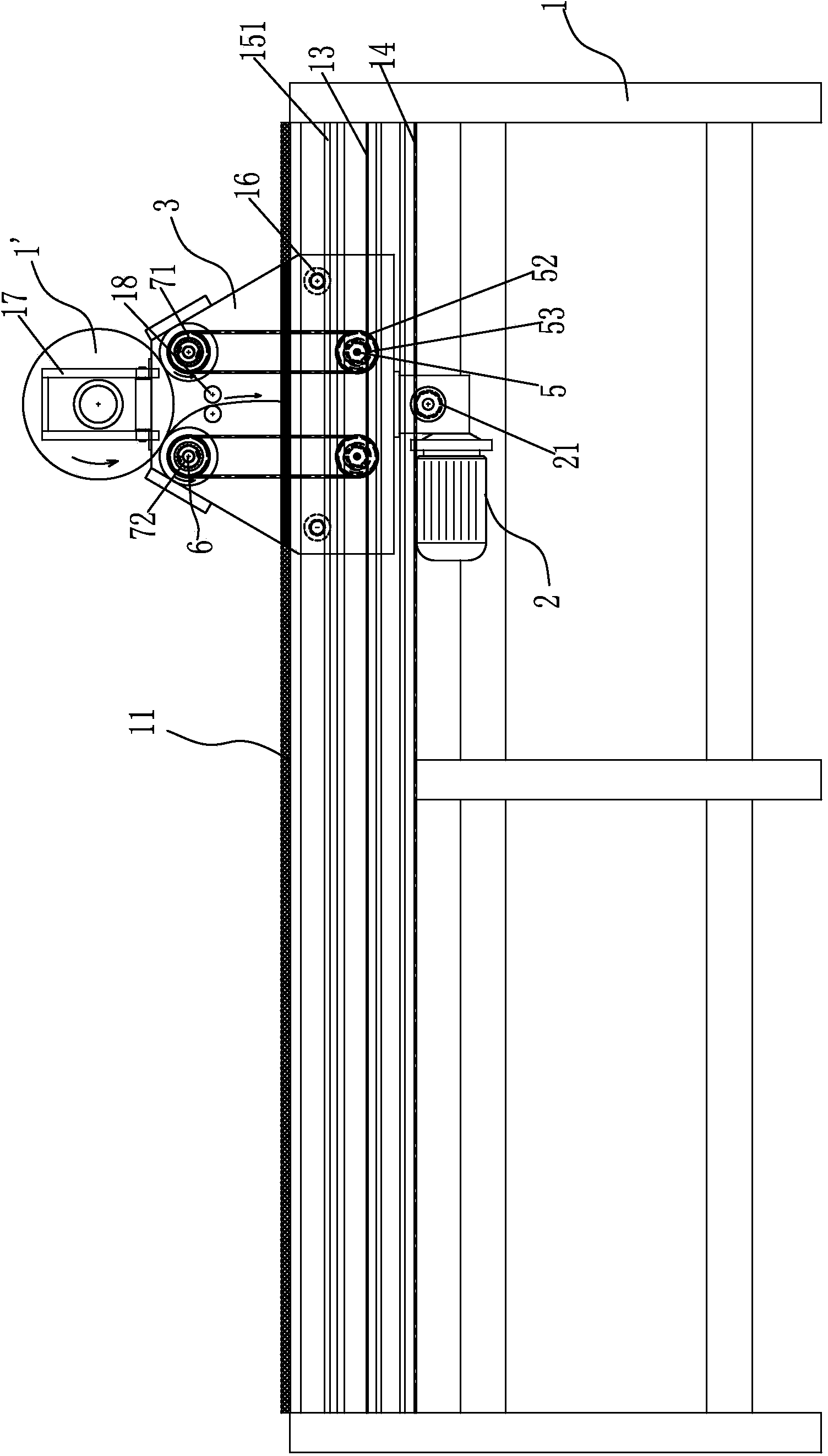
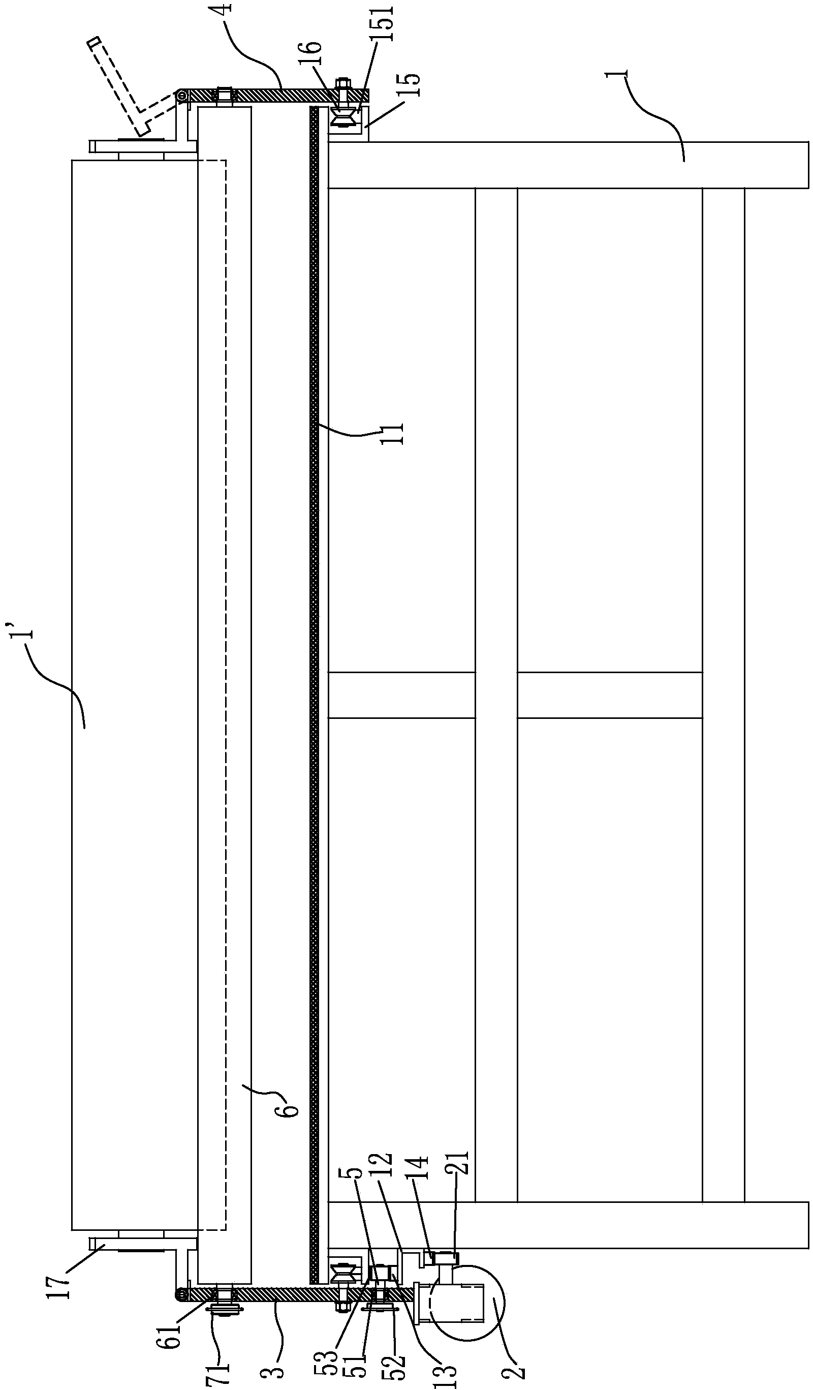
[0017] refer to figure 1 with image 3 , the present embodiment discloses a cloth automatic flattening and cutting machine, comprising a frame 1, a gear motor 2, a left wall panel 3, a right wall panel 4, and left and right cloth guide wheel groups. There is a cutting plate 11, and one side of the frame 1 is fixed with a tooth row seat 12, and the upper and lower sides of the tooth row seat 12 are respectively fixed with an upper tooth row 13 and a lower tooth row 14, and the left wallboard 3 is located on one side of the frame 1 and can slide left and right along the side of the frame 1. The deceleration motor 2 is fixed under the left wallboard 3, and the output shaft of the deceleration motor 2 is provided with a travel gear 21. The gear 21 meshes with the lower row of teeth 14, and the left wall board 3 is located on the top of the gear row seat 12, and the left and right sides are respectively rotatably provided with driving shafts 5. Between the driving shafts 5 and the...


PUM


Abstract

The invention provides a cutting machine with cloth automatically laid smooth. The cutting machine with cloth automatically laid smooth comprises a rack, a cutting pate is arranged above the rack, an upper tooth row and a lower tooth row are fixed to one side of the rack, a left wall plate and a right wall plate can slide left and right along the two sides of the rack, a speed reducing motor is fixedly arranged below the left wall plate, a walking gear of the sped reducing motor is meshed with and in linkage with the lower tooth row, the left side and the right side of the left wall plate are respectively provided with a driving shaft in a rotatable and penetrated mode, the outer end of each driving shaft is provided with a driving chain wheel, the inner end of each driving shaft is provided with a feeding gear which is meshed with and in linkage with the upper tooth row, cloth guide roll shafts are parallel to one another and arranged between the left wall plate and the right wall plate at intervals, each ratchet set comprises an outer sleeve and an inner sleeve, chain wheel teeth are arranged on an outer ring of each outer sleeve, ratchet teeth are arranged on an inner ring of each outer sleeve, tooth tips of ratchet teeth of all the outer sleeves are respectively arranged oppositely, all the inner sleeves are respectively arranged on the cloth guide roll shafts, grooves are symmetrically formed in the outer sides of the inner sleeves, a movable block is hinged to one end of each groove, a free end of each movable block abuts against the ratchet tooth of the corresponding outer sleeve, and a compressed spring is arranged between each groove and the corresponding movable block.

Description

technical field [0001] The invention relates to a cloth cutting machine, in particular to a cloth automatic flattening and cutting machine. Background technique [0002] In fabric processing, it is necessary to cut a piece of cloth raw material into a piece of cloth. The current method is to spread the cloth manually or manually cut it, or use some mechanical equipment to cut it. High labor intensity, time-consuming and labor-intensive, low production efficiency, and the flatness of the cloth after auxiliary leveling is poor, the cutting effect is not good, and it cannot meet the mass production of the assembly line. Contents of the invention [0003] In view of the above problems, the present invention proposes a cloth automatic flattening and cutting machine with reasonable structure, high production efficiency, time-saving and labor-saving, and improved cutting quality. [0004] In order to solve this technical problem, the technical solution of the present invention i...

Claims


Application Information

Patent Timeline
IPC IPC(8): D06H7/00
Inventor 吕子利吕自力
Owner FUJIAN DALIYA CLOTHING TECH
Why Eureka
Try Eureka