Composite column composite beam frame with built-in tube high-strength concrete core column and its construction method

A technology of high-strength concrete and construction methods, which is applied in the direction of architecture and building construction, can solve the problems of difficult layout of prestressed tendons and large cross-sectional dimensions, and achieve the goals of shortening the construction period, improving axial compression performance, and reducing deformation and cracks Effect

Inactive Publication Date: 2016-06-01
NORTHEAST GASOLINEEUM UNIV
View PDF4 Cites 0 Cited by
  • Summary
  • Abstract
  • Description
  • Claims
  • Application Information

AI Technical Summary

Problems solved by technology

[0003] The purpose of the present invention is to provide a composite column composite beam frame with a built-in tube high-strength concrete core column, which is used to solve the problem that the existing general reinforced concrete column has a large section size and the prestressed tendons in the composite beam are difficult to arrange at the nodes. Another object of the invention is to provide a construction method for this composite column composite beam frame with built-in high-strength concrete core columns

Method used


Image

  • Composite column composite beam frame with built-in tube high-strength concrete core column and its construction method
  • Composite column composite beam frame with built-in tube high-strength concrete core column and its construction method
  • Composite column composite beam frame with built-in tube high-strength concrete core column and its construction method

Examples


Embodiment 1

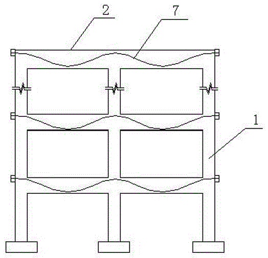
[0047] like figure 1 As shown, the composite column composite beam frame with built-in tube high-strength concrete core column has a built-in asymmetrical steel or plastic bone prestressed concrete composite beam 2, a reinforced concrete composite column 1 with a built-in core column, and the composite beam 2 is arranged horizontally Between the combined columns 1, the two are connected by nodes at the intersection. The core column 3 is placed in a reinforced concrete column. combine Figure 8 , Figure 15 As shown, the prestressed tendon 7 at the beam-column node passes through both sides of the core column 3, and is stretched and anchored at the end of the composite column. The H-shaped steel or plastic bone in the composite beam 2 is connected to the core column 3 through double-half snap rings 6 fixed connections, see Figure 9 . In this embodiment, the same type of concrete is used for the core column 3 and the reinforced concrete column on its outer side.

[0048] ...

Embodiment 2

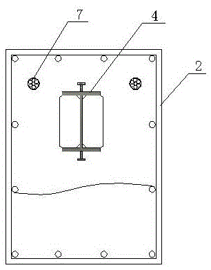
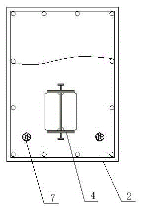
[0061] This composite column composite beam frame with built-in tube high-strength concrete core column has a built-in asymmetrical steel or plastic bone prestressed concrete composite beam 2, a reinforced concrete composite column 1 with a built-in core column 3, and the composite beam 2 is horizontally arranged on the composite beam. Between the columns 1, the two are connected by nodes at the intersection; the core column 3 is a steel tube concrete column or FRP tube concrete column; the core column 3 is placed in a reinforced concrete column; the cross-section of the composite beam 2 is rectangular, and the steel frame 4 or The plastic bone is H-shaped, the steel frame 4 or plastic bone is provided with transverse stiffeners 5, the steel frame 4 or plastic bone is located at the lower part of the composite beam 2 at the mid-span, and the steel frame 4 or plastic bone at the support is located at the upper part of the composite beam 2 , the prestressed tendons 7 are set in t...

Embodiment 3

[0070]This composite column composite beam frame with built-in tube high-strength concrete core column has a built-in asymmetrical steel or plastic bone prestressed concrete composite beam 2, a reinforced concrete composite column 1 with a built-in core column 3, and the composite beam 2 is horizontally arranged on the composite beam. Between the columns 1, the two are connected by nodes at the intersection; the core column 3 is a steel tube concrete column or FRP tube concrete column; the core column 3 is placed in a reinforced concrete column; the cross-section of the composite beam 2 is rectangular, and the built-in steel frame 4 or the plastic bone is H-shaped, the steel frame 4 or the plastic bone is provided with transverse stiffeners 5, the steel frame 4 or plastic bone is located at the lower part of the composite beam 2 at the mid-span, and the steel frame 4 or plastic bone is located at the composite beam 2 at the support The prestressed tendons 7 are arranged in the ...


PUM


Abstract

The invention relates to a combination column and combination beam frame with internally-arranged pipe high-strength concrete core columns and a construction method of the combination column and combination beam frame. The combination column and combination beam frame with the internally-arranged pipe high-strength core columns is provided with internally-arranged asymmetric steel rib or plastic rib prestressed concrete combination beams and reinforcing bar concrete combination columns with the internally-arranged core columns, the combination beams are horizontally arranged between the combination columns, and the combination beams are connected with the combination columns at intersections through joints. The core columns are steel pipe concrete columns or FRP pipe concrete columns, shearing keys for resisting concrete sliding are arranged on the outer walls of the core columns, and the core columns are placed in the reinforcing bar concrete columns. Transverse stiffening ribs are arranged on steel ribs or plastic ribs in the combination beams, the steel ribs or the plastic ribs at the midspan positions are arranged on the lower portions of the combination beams, the steel ribs or the plastic ribs on supports are arranged on the upper portions of the combination beams, and prestressed ribs are arranged in the combined beams in the length direction. The prestressed ribs on the beam and column joints penetrate through two sides of the core columns, and are tensioned and anchored at the ends of the combination columns. The axial pressure capable of being borne by the frame is large, and too wide columns are prevented from existing in a system; the prestressed ribs are blended in the combination beams, and the deformation and cracks of the combination beams can be reduced.

Description

technical field [0001] The invention relates to a building frame structure in the field of civil engineering structures, in particular to a composite column composite beam frame with a built-in tube high-strength concrete core column and a construction method thereof. Background technique [0002] Conventional building frame structures are mostly reinforced concrete frames and steel frames, the achievable spans are small, and the bearing capacity of components is low, which has great limitations in practical engineering applications. In recent years, with the development of higher buildings, larger spans and heavy loads, conventional structural systems are facing new challenges. People began to build a structural system with greater rigidity and stronger bearing capacity. Steel bones were added to the concrete, and the concrete and steel bones were bonded together to form a combined structure with high rigidity and convenient construction. Due to the deficiencies and defect...

Claims


Application Information

Patent Timeline
Patent Type & Authority Patents(China)
IPC IPC(8): E04B1/30
Inventor 计静姜良芹张文福刘迎春袁朝庆卢召红
Owner NORTHEAST GASOLINEEUM UNIV
Why Eureka
Try Eureka