Flow guiding or flow leading type automatic drainage waterproof system
A self-draining and drainage ditch technology, applied in the direction of condensate water discharge, roofing, construction, etc., can solve the problems of short waterproof life, stagnant water drainage, difficult construction of drainage ditch, etc., to achieve long waterproof life, improve drainage capacity, reduce The effect of construction difficulty
- Summary
- Abstract
- Description
- Claims
- Application Information
AI Technical Summary
Problems solved by technology
Method used
Image

Examples
Embodiment 1
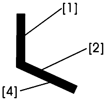
[0053] Example 1: Combining figure 1 , Figure 10 , Figure 11 , Figure 12 , Figure 18 , it is advisable to use materials with surface infiltration phenomenon to process hydrophilic diversion curved surfaces or slopes with appropriate slopes such as semi-arc, semi-∩, semi-∧-shaped and other shapes on the backwater surface [4] as the diversion structure Flashing sheet [2], such as figure 1 shown; or on the surface of the vertical sheet [1] of the diversion flashing sheet [2] that is processed with materials such as metals, plastics, etc. surface and diversion curved surface or inclined surface [4] add a layer of hydrophilic material with surface wetting phenomenon, such as Figure 10 shown; or on the surface of the vertical sheet [1] of the diversion flashing sheet [2] that is processed with materials such as metals, plastics, etc. surface and diversion curved surface or inclined surface [4] paste a layer of hydrophilic fiber or fabric [7] and other materials that are s...
Embodiment 2
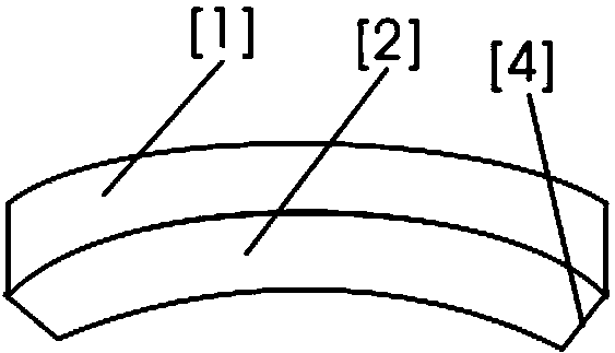
[0058] Example 2: Combining Figure 4 , Figure 7 , Figure 9 , it is on the basis of embodiment 1, processing the diversion flashing sheet [2] into a circular diversion flashing circle [25], such as Figure 4 As shown, the circular diversion flashing ring [25] can be used to separate the circular vertical surfaces such as exhaust pipes and water pipes from the water flow, reduce the construction difficulty of the waterproof layer around the circular exhaust pipes and water pipes, and improve the work efficiency. Efficiency; In order to improve the stability of the circular diversion flashing ring [25] on the circular exhaust pipe and water pipe or to the waterproof protection effect of the lower exhaust pipe and water pipe, the circular diversion flashing ring [25] ]’s diversion curved surface or the end of the slope [4] and then process a vertical ring [3], the vertical ring [3] can be directly supported on the ground, when the vertical ring [3] and the ground sealing perf...
Embodiment 3
[0059] Example 3: Binding Figure 14 , Figure 15 , Figure 16 , Figure 17 , it is installed vertically on the vertical glass curtain wall or wall such as Figure 14 The water flow control member [14] of the hydrophilic drainage strip [13] with fibers or fabrics that can prevent the water flow on the wall from flowing freely in the horizontal direction, that is, on the left and right interfaces, makes the glass curtain wall or wall The water flow cannot cross the water flow control part [14] laterally when flowing downward, but can only be absorbed and guided downward by the same side of the water flow control part [14] or by the hydrophilic drainage strip [13], effectively controlling the water flow In order to improve the drainage effect, the glass curtain wall or wall surface near the hydrophilic drainage strip [13] can be processed into a hydrophobic surface or treated with hydrophobicity; in order to prevent the hydrophilic drainage strip [13] from being directly expo...
PUM
 Abstract
Description
Claims
Application Information