Sanitary installation part and component of a sanitary water faucet and method for controlling flow of flowing medium

A built-in, hygienic technology, which is applied in indoor sanitary pipeline installations, temperature control without auxiliary power supply, flow control, etc., can solve the problems of increased bacterial load, prolonged hot water outflow, consumption, etc., to avoid mechanical load effect

Active Publication Date: 2014-08-06
NEOPERL
View PDF6 Cites 4 Cited by
  • Summary
  • Abstract
  • Description
  • Claims
  • Application Information

AI Technical Summary

Problems solved by technology

This can lead, in particular, to an increased bacterial load of the transported water or other medium, especially in hot water pipes which are not permanently kept at temperature and are cooled between use cycles
Furthermo

Method used


Image

  • Sanitary installation part and component of a sanitary water faucet and method for controlling flow of flowing medium
  • Sanitary installation part and component of a sanitary water faucet and method for controlling flow of flowing medium
  • Sanitary installation part and component of a sanitary water faucet and method for controlling flow of flowing medium

Examples


Embodiment Construction

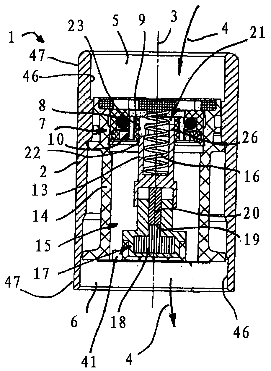
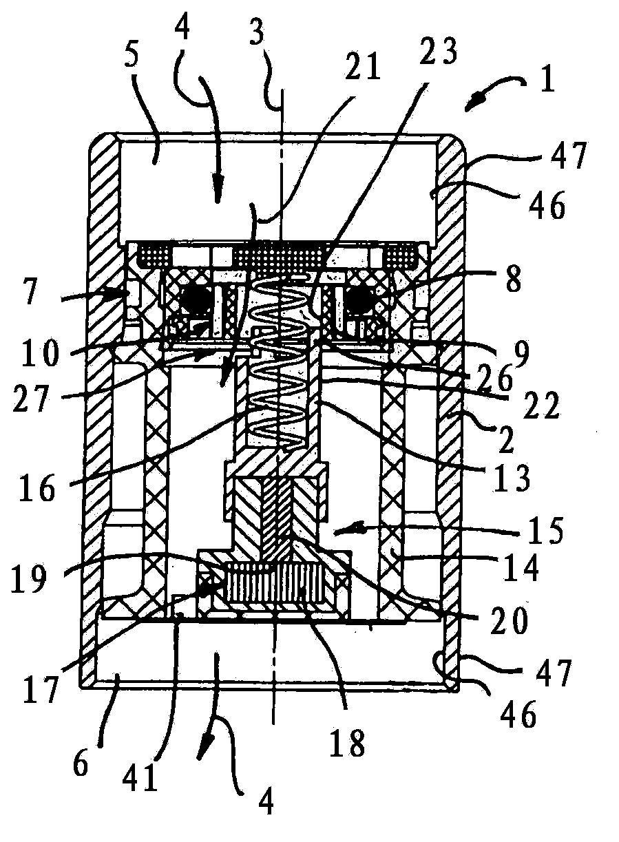
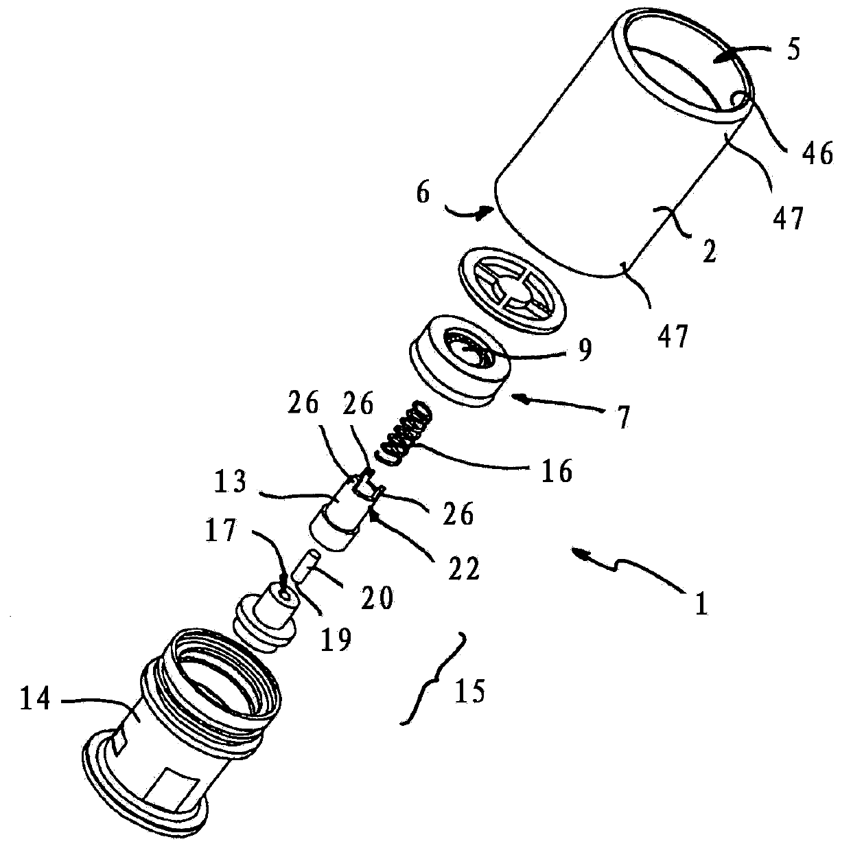
[0085] figure 1 A sanitary insert according to the invention, generally designated 1 , is shown in axial section.

[0086] The insert part 1 is designed with a tubular insert sleeve 2 as a cylinder, in particular inserted into the cylinder.

[0087] In the example shown, an axis 3 of the cylindrical insert sleeve 2 defines a flow path 4 whose flow direction is figure 1 The center extends between an inlet 5 and an outlet 6 from top to bottom.

[0088] Between the inlet 5 and the outlet 6 , in the throughflow path 4 , a functional unit 7 is formed, which realizes the volume flow dependence of the quantity adjustment function in a manner known per se with a resistance body 8 (an O-ring). . Here, the resistance body 8 is pressed against a receptacle 9 with varying degrees of intensity depending on the pressure prevailing at the inlet 5 or depending on the pressure falling on the functional unit 7 between the inlet 5 and the outlet 6, so as to form a The pressure-dependent cros...


PUM


Abstract

The invention relates to a sanitary installation part (1) which, along with a functional unit (7), forms a quantity regulator, it is proposed that a regulating element (13), which can be adjusted along an adjustment path, be coupled to a temperature-sensitive drive unit (15) such that different regulating positions of the regulating element (13) are set in dependence on the temperature of the medium flowing through the installation part (1), wherein the different regulating positions realize in each case different volume-flow dependencies (11, 12, 45, 48) and/or flow resistances (cf. figure 1).

Description

technical field [0001] The invention relates to a sanitary insert comprising a functional unit arranged in a flow path, which enables a pressure-dependent definition of the volume flow as a volume flow dependence (volume flow function). [0002] Furthermore, the invention relates to a component of a sanitary tap. [0003] Finally, the invention relates to a method for controlling the flow of a flowing medium, in particular flowing water. Background technique [0004] Such inserts are known in sanitary technology as flow regulators and serve to save water. [0005] The known flow regulators result in an increased residence time of water or other liquid medium in the water line. This can lead, in particular, to an increased bacterial load of, in particular, the transported water or other medium in hot water pipes which are not permanently kept at temperature and are cooled between use cycles. Furthermore, in the case of cooled hot water pipes, the time from opening the tap ...

Claims


Application Information

Patent Timeline
IPC IPC(8): F16K31/64
CPCE03C1/041E03C1/08F16K31/002G05D7/012G05D23/022E03C2001/026E03C1/01F16K31/02E03C1/04F16K31/00F16K3/08G05D23/08
Inventor M·滕佩尔C·魏斯
Owner NEOPERL
Why Eureka
Try Eureka