Axial-flow type maze throttling structure
An axial-flow and labyrinth technology, applied to valve details, valve fluid energy-absorbing devices, engine components, etc., can solve the problems of cavitation damage, difficult to exceed ten levels, high cost, etc., and achieve good throttling and speed reduction, The effect of low manufacturing cost and small number of parts
- Summary
- Abstract
- Description
- Claims
- Application Information
AI Technical Summary
Problems solved by technology
Method used
Image
Examples
Embodiment 1
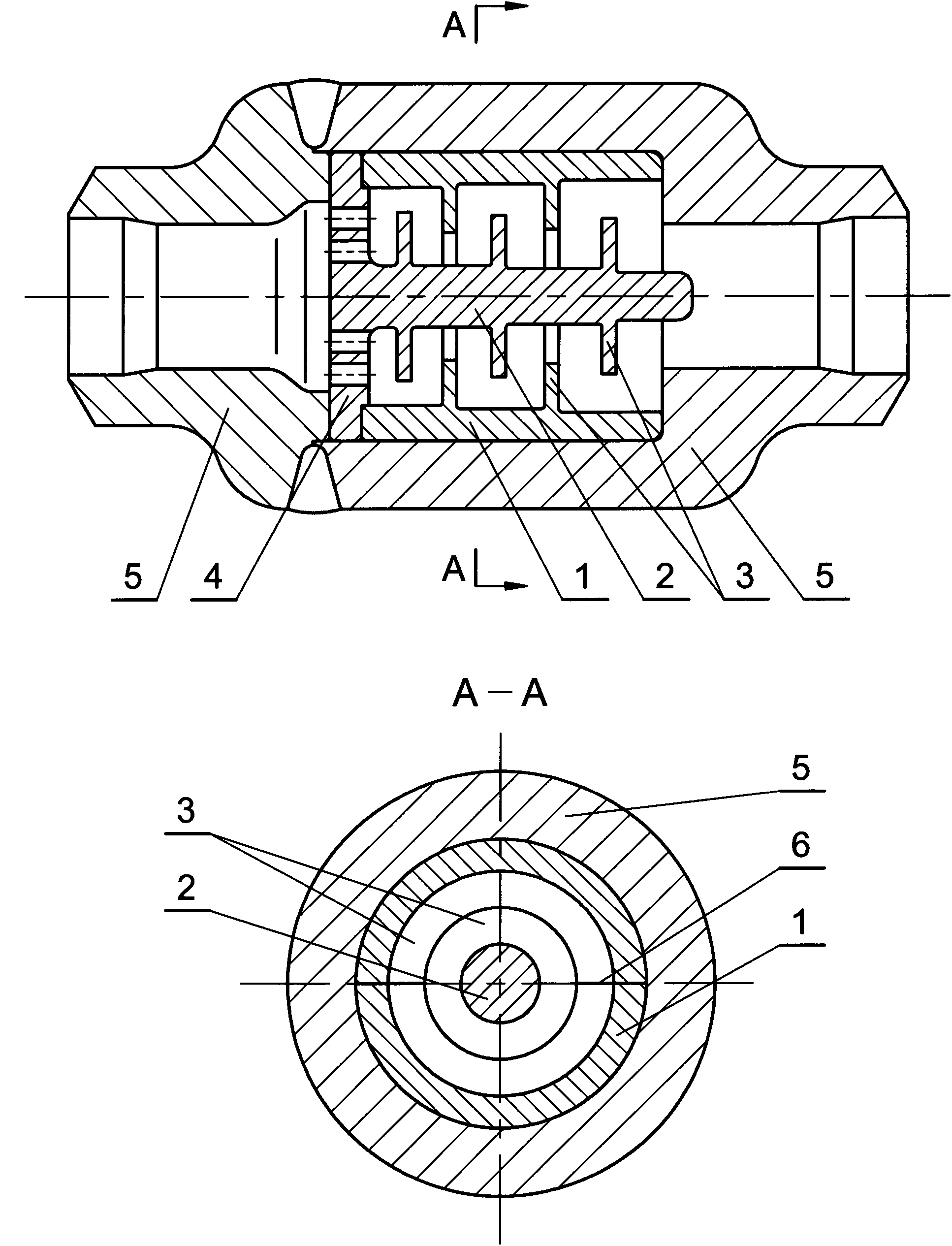
[0016] Such as figure 1 Shown is a schematic diagram of one embodiment of the present invention. The specific technical solution is: the outer pressure bearing body (5) is assembled and welded by two parts, and the two ends are respectively provided with a fluid inlet and a fluid outlet; The flow assembly consists of two components, the labyrinth jacket (1) and the labyrinth inner core (2). The labyrinth jacket (1) and the labyrinth inner core (2) are rotary parts whose centerlines coincide. The inlet and outlet lines of the body (5) coincide, the labyrinth inner core (2) is at the center of the labyrinth throttling assembly and the labyrinth coat (1) surrounds the outer periphery of the labyrinth inner core (2), and the space between the two The cavity is connected with the inlet and outlet of the outer pressure-bearing body (5) to form the flow channel of the throttling structure; the basic shape of the labyrinth jacket (1) is a multi-stage cylinder with multiple plates in ...
Embodiment 2
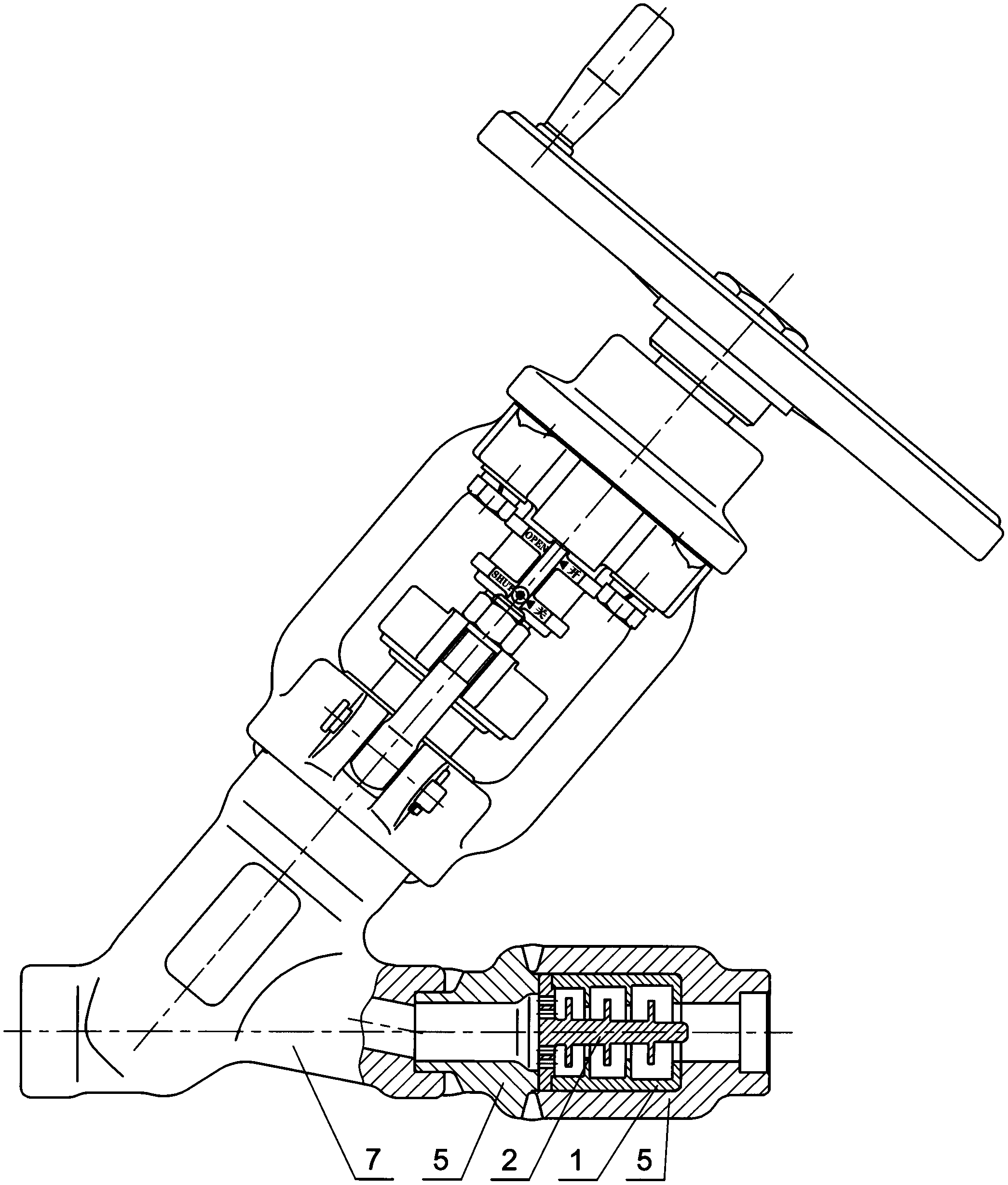
[0018] Adopting the technical solution of the axial-flow labyrinth throttling structure proposed by the present invention can be made into an independent component—the axial-flow labyrinth throttle, which can be used as a pipeline accessory. Such as figure 2 Shown is a schematic diagram of the axial flow labyrinth restrictor used in conjunction with the valve, the inlet of the axial flow labyrinth restrictor and the valve outlet are connected by welding, the medium enters the valve from the left, and the right end of the axial flow labyrinth restrictor is Media outlet.
[0019] The number of diaphragms on the labyrinth coat (1) and the labyrinth inner core (2) of the axial flow labyrinth restrictor determines the number of stages of the labyrinth throttling structure. The number of diaphragms is 2, the number of diaphragms on the inner core (2) of the labyrinth is 3, and the number of turns of the labyrinth throttling structure is 12, which is based on the working pressure d...
Embodiment 3
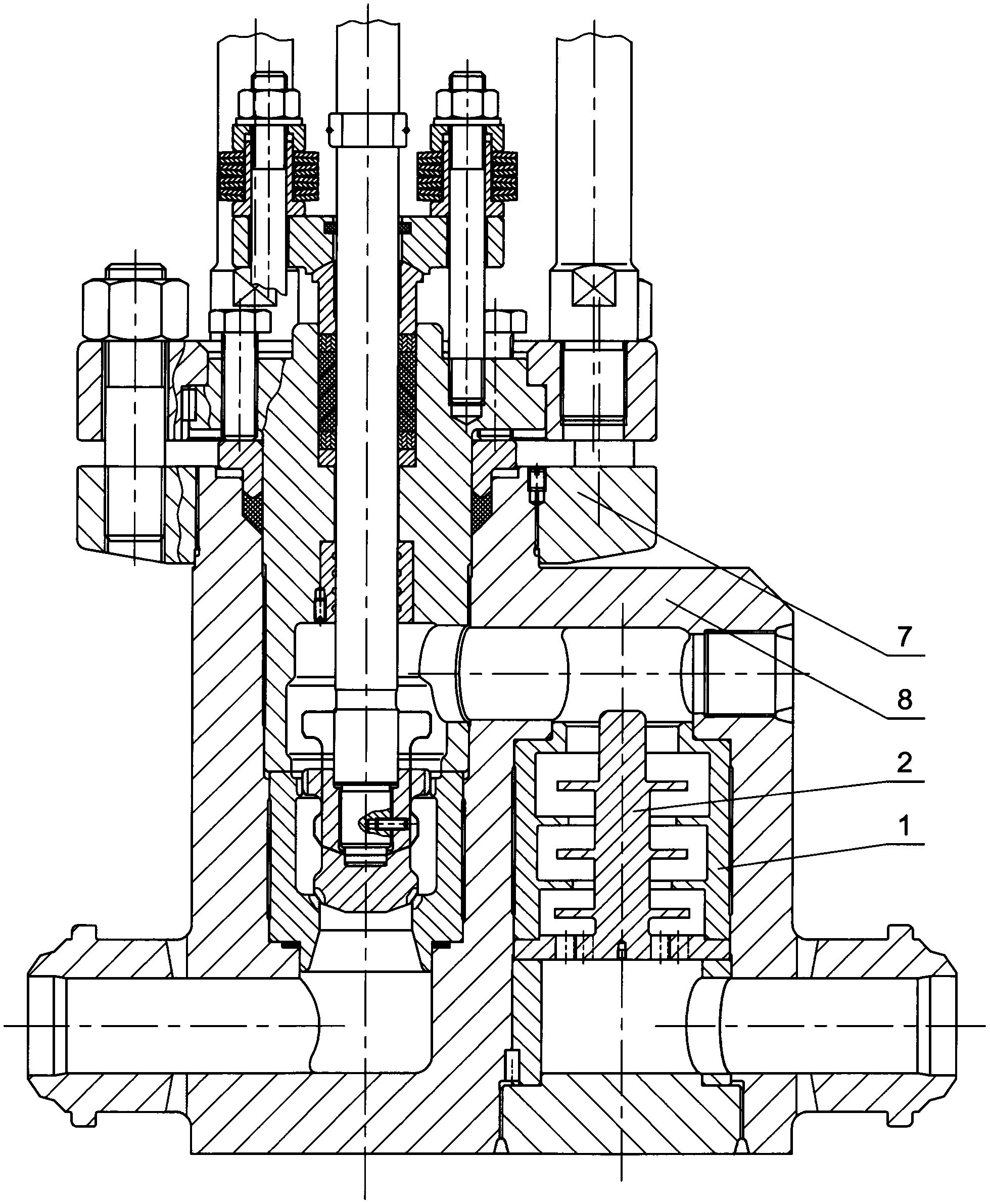
[0021] The axial-flow labyrinth throttling structure proposed by the present invention can also be designed inside the valve as a part of the valve structure, such as image 3 shown.
[0022] The valve (7) of this embodiment is used for boiler boiler water blowdown, because the inlet medium is the high-pressure boiler water in the steam drum, the outlet is open to the atmosphere, and the valve has a high working pressure difference, so it is located on the inlet side of the valve body (8). A built-in axial-flow labyrinth throttling structure is set, so that the medium passing through the sealing surface of the valve is water with low pressure and low flow rate, so as to solve the problem of serious leakage of the sealing surface of the high-pressure differential blowdown valve of the power plant boiler due to erosion. The problem of short service life of the valve and high vibration and noise.
[0023]Since the flow area of the labyrinth channel of the axial-flow labyrinth ...
PUM
 Abstract
Description
Claims
Application Information
 - R&D
- Intellectual Property
- Life Sciences
- Materials
- Tech Scout
- Unparalleled Data Quality
- Higher Quality Content
- 60% Fewer Hallucinations
Browse by: Latest US Patents, China's latest patents, Technical Efficacy Thesaurus, Application Domain, Technology Topic, Popular Technical Reports.
© 2025 PatSnap. All rights reserved.Legal|Privacy policy|Modern Slavery Act Transparency Statement|Sitemap|About US| Contact US: help@patsnap.com


