Rotary type exhaust gas processing device

A waste gas treatment device and technology for waste gas treatment, which are applied in combustion methods, lighting and heating equipment, combustion types, etc., can solve the problems of increased energy consumption of equipment, waste of manpower, inability to eliminate the impact of damper valve gas and increased concentration of exhaust gas, etc. , to achieve the effect of temperature and maintenance saving

Inactive Publication Date: 2014-08-06
JIANGSU ZHAONIAN INTELLIGENT TECH CO LTD
View PDF7 Cites 2 Cited by
  • Summary
  • Abstract
  • Description
  • Claims
  • Application Information

AI Technical Summary

Problems solved by technology

When switching, it is easy to cause the impact of gas in the pipeline and the mixing of untreated gas and treated gas
Also because the stability of switching valves in high-temperature environments is reduced, it is easy to cause the equipment to fail to work normally.
Due to the high temperature of the pipeline and the heat preservation of the pipeline valve, it is not easy to perform maintenance, and the maintenance time is long, which wastes manpower
After the high-temperature valve is used for a period of time, the replacement and cleaning work is also very cumbersome, resulting in an increase in the workload and cost of replacement
The above situations will also lead to an increase in equipment energy consumption and the processed gas cannot meet the national emission standards
At present, there is no waste gas treatment device on the market that can overcome these shortcomings, and the effective work of the waste gas treatment device can only be ensured through continuous maintenance on site.
However, these measures cannot eliminate the gas impact and the increase in exhaust gas concentration during the switching process of the damper.

Method used


Image

  • Rotary type exhaust gas processing device

Examples


Embodiment Construction

[0017] The present invention will be further described below in conjunction with the accompanying drawings.

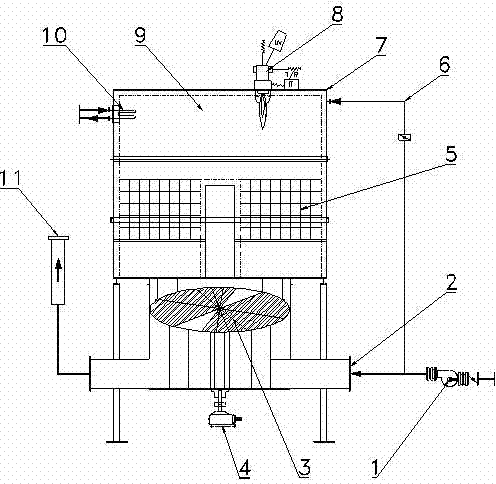
[0018] Such as figure 1 As shown, a rotary exhaust gas treatment device includes a chamber body 7, the upper end of the chamber body 7 is an exhaust gas treatment area 9, and the lower end is a heat storage and heat exchange area 5. Rotary wheel 3, the two sides below the rotary wheel 3 are respectively provided with an air inlet pipe 2 and an exhaust air pipe 11, the air inlet of the air inlet pipe 2 is provided with an air inlet fan 1, and the waste gas treatment area 9 Also be provided with heating burner 8 inside. The rotary wheel 3 rotates continuously under the drive of the rotary reducer 4, and periodically transports the exhaust gas to the heat storage and heat exchange area 5, which overcomes the shock and vibration caused by switching the air duct switch with the valve before; it also keeps the exhaust gas treatment continuous To avoid the discharge of untr...


PUM


Abstract

The invention discloses a rotary type exhaust gas processing device. The rotary type exhaust gas processing device comprises a chamber body, wherein the upper end part of the chamber body is provided with an exhaust gas processing region, and the lower end part of the chamber body is provided with a heat storing and heat exchanging region; a rotating wheel is arranged below the chamber body, two sides below the rotating wheel are provided with an air inlet pipe and an exhaust air pipe, respectively, an air inlet of the air inlet pipe is provided with an air inlet fan, and the exhaust gas processing region is internally provided with a heating burning machine. Exhaust gas is periodicity conveyed to the heat storing and heat exchanging region through the continuous rotation of the rotating wheel, so that shock vibration generated by opening and closing an air channel through a valve is eliminated; exhaust gas treatment keeps continuous all the time, so that the condition that untreated exhaust gas is discharged because of the switching of the air channel valve and discharged gas can not meet a discharging requirement of China is avoided, exhaust gas is treated continuously, up-to-standard purified gas is continuously discharged, and environmental requirements of China are met.

Description

technical field [0001] The invention relates to a rotary exhaust gas treatment device. In particular, it relates to a high-efficiency, energy-saving, continuous and up-to-standard rotary waste gas treatment device. Background technique [0002] The exhaust gas treatment device is a device that relies on the heat storage heat exchange area and the exhaust gas treatment area, and the exhaust gas passes through the heat storage heat exchange area and the exhaust gas treatment area. A treatment method in which the regenerative heat exchange area and the exhaust gas treatment area perform preheating, purification and heat exchange on the passing exhaust gas. In the regenerative heat exchange area, when the exhaust gas passes through, the exhaust gas absorbs the heat in the heat storage body, the temperature of the exhaust gas rises, and the exhaust gas is transported to the exhaust gas treatment area, where the exhaust gas further absorbs heat energy and burns and cracks. The g...

Claims


Application Information

Patent Timeline
Patent Type & Authority Applications(China)
IPC IPC(8): F23G7/06
Inventor 何群伟
Owner JIANGSU ZHAONIAN INTELLIGENT TECH CO LTD
Why Eureka
Try Eureka