[0033] The present invention will be described below in conjunction with the drawings.
[0034] In the following description, some specific details provide those skilled in the computer field with an overall understanding of the present invention. In the embodiments, the elements that implement specific functions are shown in the form of schematic diagrams or block diagrams, so as to highlight the technical key points without obscuring the present invention in unnecessary details. For example, since the understanding of those of ordinary skill in the art covers common-sense details that are disclosed in the art, such as network communication, electromagnetic signal command technology, user-end interface or input/output technology, etc., in the embodiments to the greatest extent The above technical details are omitted above, and these details are not considered to be necessary features for obtaining the complete technical solution of the present invention.
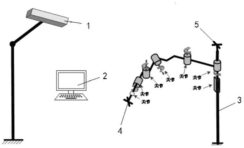
[0035] Such as figure 1 As shown, the calibration system of the present invention includes an optical positioner 1 and a host computer 2 connected to each other. When in use, a target ball hole is set on each arm of the robot 3 to install the target ball, and the target ball is calibrated by the optical positioner 1 The relative position of the robot 3 is then calculated. The optical positioner 1 is continuously adjusted under the control of the upper computer 2 so that the measured point is within the optimal measurement range of the optical positioner, and the measured structural parameters are input into the upper computer 2; The pose is controlled, and the DH parameters are corrected using the absolute positioning error calibration method of the present invention, the kinematic model of the robot 3 is accurately calculated, and the joint transmission backlash and zero error of the calculated robot are analyzed and compensated. The optical positioner 1 of this embodiment is preferably an NDI optical navigator.
[0036] The following describes the absolute positioning error calibration method of the present invention by taking a tandem robot manipulator as an example. Such as figure 2 As shown, the tandem articulated robot in this embodiment is a robot with a six-degree-of-freedom manipulator, and the parameters of each joint of the manipulator are shown in the following table:
[0037] Joints
[0038] 4
[0039] Among them, the joint connected to the positioning bracket 4 is a mobile joint, and the other joints are rotating joints; the arm close to the registration bracket 5 is called a big arm, and the arm close to the positioning bracket 4 is called a small arm. The absolute positioning error calibration method of the present invention mainly includes three aspects: D-H parameter correction, joint transmission backlash error analysis and compensation, and zero error calibration:
[0040] 1) Correction of D-H parameters
[0041] In this embodiment, the big arm 12 is taken as an example for analysis, and the steps include:
[0042] i) Fix the optical positioner 1 in the calibration system at a distance of 2~3m from the robot 3; figure 2 As shown, the target ball is fixed on the arm 12 of the robot 3, and the position of the target ball at this time is recorded by the optical positioner 1;
[0043] ii) Move joint A alone, and under the condition that the other joints are not moving, make the boom l2 rotate every 10° to record the position coordinates of the target ball on the boom l2 through the optical positioner 1, and fit the circle center C1;
[0044] iii) Similarly, adjust the fixed position and height of the target ball on the boom l2, repeat step ii) to fit the center C2 corresponding to the fixed position, and then continuously adjust the target ball to obtain a series of different fixed positions and heights The center sets C1, C2...; then the center sets C1, C2... are fitted to approximate a straight line Z1; Z1 is the arm joint axis;
[0045] iv) Control the robot 3 to return to the initial position, move the joint B alone, and make the forearm 13 rotate every 10° to record the position coordinates of the target ball on the forearm 13 through the optical positioner 1 under the condition that the other joints are not moving. Conjoin the center C1';
[0046] v) In the same way, adjust the fixed position and height of the target ball on the forearm l3, then continuously adjust the target ball and repeat steps iv), a series of center sets C1', C2' corresponding to different fixed positions and heights can be obtained... , And then fit the forearm joint axis Z2;
[0047] The method of fitting the center of the circle and fitting the axis is the least square method;
[0048] vi) Calculate the big arm axis Z1 and the forearm axis Z2, which reflect the axis position and posture of the big arm and forearm joints, in the distance and angle algorithm of the space straight line, and the correction arm of the big arm l2 and the forearm l3 can be obtained Parameters, for example:
[0049] Such as Figure 4 As shown, MATLAB is used to solve the big arm joint axis Z1 and the forearm joint axis Z2 in sequence, and the axis equations about joint A and joint B are obtained in space, and then the shortest distance is solved for the actual lever length of the big arm l2 Parameter, the actual angle parameter is the calculated angle between the axis of joint A and joint B.
[0050] 2) Joint transmission backlash calibration
[0051] On the one hand, due to the gear backlash and gear transmission error, the code disk reading cannot accurately reflect the actual motion of the joint; on the other hand, the factors that cause the joint transmission backlash are nonlinear, and it is difficult and complicated to accurately model. Therefore, the fast training method of the present invention based on the Levenberg Marquardt numerical optimization technology compensates the transmission backlash error of each joint, thereby improving the positioning accuracy of the robot. In addition, for robot joints that adopt gear transmission, for different meshing positions and different motion directions, the joint transmission backlash error will be different.
[0052] The present invention uses the actually measured training sample data to train the Levenberg Marquardt neural network. After the training is completed, the gear backlash is obtained, and the current position θ of the joint j relative to the joint zero position is obtained. j And the desired direction of rotation S j As the input of the Leven berg Marquardt neural network, the reading of the encoder relative to the zero position is the target rotation angle θ of the motor m As the output of the neural network, the motor is controlled to realize the compensation of the gear backlash. The rotation direction of joint j is defined as:
[0053]
[0054] The methods for obtaining training samples for building the Leven berg Marquardt neural network include:
[0055] I) Control joint j to reach the zero position;
[0056] II) Control joint j to move forward in steps of 10 degrees on the code disc. After each movement, use measuring equipment such as an optical positioner or laser tracker to measure and record the actual rotation angle of joint j until joint j moves to Positive limit position; record each step length and its corresponding actual rotation angle, as a positive training sample set;
[0057] III) Control joint j again to reach the zero position;
[0058] IV) Control joint j to move in the negative direction according to a 10-degree step on the code disc. After each movement, measure and record the actual rotation angle of joint j with a measuring device until joint j moves to the negative limit position; record each step The length and its corresponding actual rotation angle are used as the negative training sample set.
[0059] Thus, the positive training sample set and the negative training sample set of each joint can be obtained. Before training, the sample data is scaled to make all the training data fall in the interval [0, 1].
[0060] 3) Zero error calibration
[0061] A prerequisite for achieving high-precision zero position positioning in the prior art is that the actual zero position sensor installation position must be strictly consistent with the ideally designed control zero position. However, it is impossible to guarantee the robot during the installation process, and there must be certain Installation deviation, so after the robot rod parameters are corrected, the error compensation of the zero sensor position must be performed.
[0062] The mathematical model of robot zero error calibration is:
[0063] q i t = q i r + Δq i - - - ( 2 )
[0064] Where: Is the nominal rotation angle (or displacement) of joint i relative to the control zero position; Is the actual rotation angle (or displacement) of joint i relative to the control zero position; Δq i Is the zero error of joint i.
[0065] Such as Figure 5 As shown, the steps of zero error calibration include:
[0066] a) The upper computer 1 sends a change motion instruction to the robot 3 to make each joint reach the mechanical zero position. At this time, the nominal rotation angle (or displacement)
[0067] b) Use the optical positioner 1 to read the position coordinates of the positioning bracket 4 pre-installed at the end of the robot 3, that is, the mechanical zero position coordinates in the optical positioner 1;
[0068] c) According to the coordinate conversion relationship between the optical positioner 1 and the robot 3, the mechanical zero coordinate of the optical positioner 1 is mapped to the robot coordinate system, and the mechanical zero position of the positioning bracket 4 in the robot coordinate system (and the control zero Position deviation), and use this position as the target point of the robot planning, combined with the inverse kinematics inverse solution to calculate the precise rotation angle (or displacement) of each joint relative to the control zero position
[0069] d) to Calculate the average value of zero error Δq i , And use it as the compensation value of the robot zero error, input it into the robot control system in the form of calibration constant and save it.
[0070] It should be pointed out that the specific implementations described above may enable those skilled in the art to understand the invention and creation more comprehensively, but do not limit the invention and creation in any way. Therefore, although this specification has described the invention and creation in detail with reference to the drawings and embodiments, those skilled in the art should understand that the invention and creation can still be modified or equivalently replaced. In short, everything does not depart from the invention and creation. The spirit and scope of the technical solutions and their improvements shall be covered by the protection scope of the invention patent.