Vortex optical fiber on basis of spiral eccentric hole integrating embedded core and preparation method thereof
A technology of optical fiber preform and partial hole, which is applied in the direction of clad optical fiber, glass manufacturing equipment, manufacturing tools, etc., can solve the problems such as the difficulty of preparing optical fiber, and achieve the effect of good spatial flexibility and simple preparation
- Summary
- Abstract
- Description
- Claims
- Application Information
AI Technical Summary
Problems solved by technology
Method used
Image

Examples
preparation example Construction
[0028] The preparation process of the optical fiber can be divided into the following steps (such as Figure 6-Figure 8 ):
[0029] Step 1: to the optical fiber preform rod 6 with core 5 (such as Figure 6 ) into an eccentric air hole 7 to form a new optical fiber preform 8 (such as Figure 7 );
[0030] Step 2: Place the optical fiber preform 8 on the drawing tower, perform torsional drawing under the joint action of the vertical traction force 9 and the torsional force 10, and prepare the helical eccentric fused-core vortex optical fiber after heating and corresponding post-processing 11 12 (the offset hole is located on the core side).
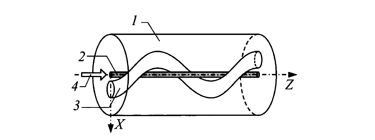
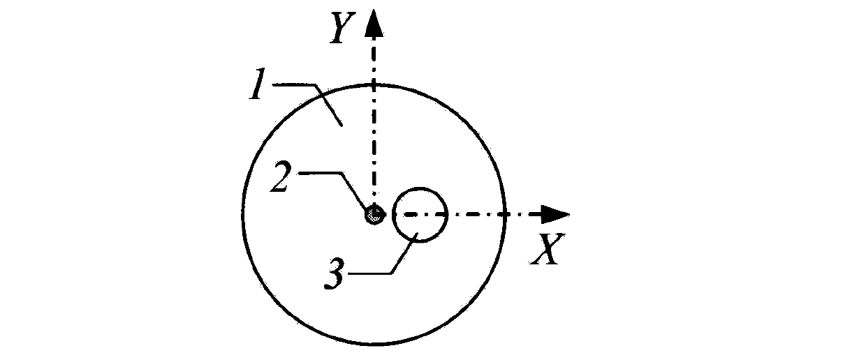
[0031] combine Figure 9-Figure 10 , the second embodiment of the present invention has a section of helical off-hole fused core vortex fiber, which includes a cladding 1, a core 2 and a single helical air hole 3, wherein the core 2 is located in the center of the fiber, and partially fused Embedded in the cladding 1 of the inner wall ...
Embodiment 1
[0037] 1. Optical fiber preparation: according to the optical fiber preparation method of the first embodiment, the helical off-hole fusion core vortex optical fiber 12 is prepared;
[0038] 2. Light source coupling: cut the prepared helical off-hole fused core-embedded vortex fiber 12, and then align and weld it with the single-mode fiber 18 with light source pigtail, such as Figure 13 shown;
[0039] 3. Generation of vortex beams: After inputting laser light 19, vortex light mode transmission will be realized in helical off-hole fused-core vortex fiber 12, and vortex-like beams can be output at the fiber end.
Embodiment 2
[0041] 1. Optical fiber preparation: according to the optical fiber preparation method of the second embodiment, the helical off-hole fusion core vortex optical fiber 17 is prepared;
[0042] 2. Light source coupling: Cut the prepared helical off-hole fused core-embedded vortex fiber 17, and then align and weld it with the single-mode fiber 18 with the light source pigtail, such as Figure 14 shown;
[0043]3. Generation of vortex beams: After inputting laser light 19, vortex light mode transmission will be realized in helical off-hole fused-core vortex fiber 17, and quasi-vortex beams can be output at the fiber end.
PUM
 Abstract
Description
Claims
Application Information
 - R&D
- Intellectual Property
- Life Sciences
- Materials
- Tech Scout
- Unparalleled Data Quality
- Higher Quality Content
- 60% Fewer Hallucinations
Browse by: Latest US Patents, China's latest patents, Technical Efficacy Thesaurus, Application Domain, Technology Topic, Popular Technical Reports.
© 2025 PatSnap. All rights reserved.Legal|Privacy policy|Modern Slavery Act Transparency Statement|Sitemap|About US| Contact US: help@patsnap.com