In-pile flow distribution device of reactor of nuclear power station

A flow distribution device and nuclear power plant reactor technology, applied in the field of nuclear power, can solve the problems that the eddy current cannot be fully mixed and cannot be effectively suppressed, and achieves the effects of good flow distribution uniformity, simple structure, and good distribution effect

Inactive Publication Date: 2014-08-06
中广核工程有限公司 +1
View PDF5 Cites 22 Cited by
  • Summary
  • Abstract
  • Description
  • Claims
  • Application Information

AI Technical Summary

Problems solved by technology

This flow distribution structure has the advantage of simple structure, but it also cannot fully mix the vortex flow at the bottom of the pressure vessel, so the vortex inside and outside the head-shaped structure 46 still cannot be effectively suppressed

Method used


Image

  • In-pile flow distribution device of reactor of nuclear power station
  • In-pile flow distribution device of reactor of nuclear power station
  • In-pile flow distribution device of reactor of nuclear power station

Examples


Embodiment Construction

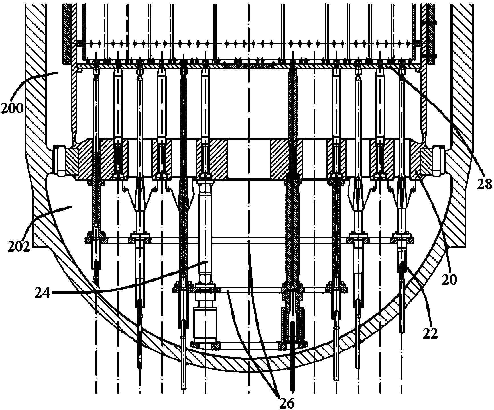
[0027] see Figure 6 and Figure 7 , the reactor flow distribution device of the nuclear power plant reactor of the present invention is installed in the lower head 90 of the pressure vessel, which includes the lower support plate 60 of the core, the surrounding basket structure, the column 80 and the energy absorber 82 . Wherein, the lower support plate 60 of the core is welded to the lower end of the hanging basket 92; The lower chamber is divided into inner and outer parts; the column 80 is vertically arranged between the basket-shaped structure and the lower support plate 60 of the core; the energy absorber 80 is installed under the basket-shaped structure.

[0028] Perforations 62 are opened on the lower support plate 60 corresponding to the position of each group of fuel assemblies.

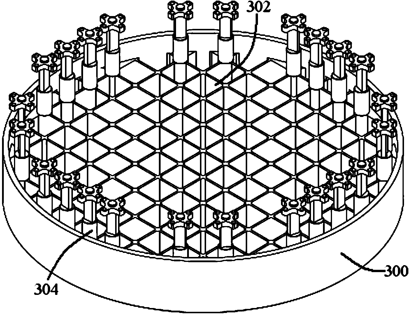
[0029] The basket-shaped structure is fixed below the core lower supporting plate 60, and its thickness is between 30 and 100 mm. The structure includes a porous surrounding basket 72, an...


PUM


Abstract

The invention discloses an in-pile flow distribution device of a reactor of a nuclear power station. The device is used for distributing flow of a reactor core coolant; the flow distribution device comprises a lower reactor core support plate, a surrounding basket-shaped structure and vertical columns, wherein the surrounding basket-shaped structure is fixed below the lower reactor core support plate and comprises a porous surrounding basket and an eddy-current confinement plate positioned at the bottom of the porous surrounding basket; a plurality of flowing holes are respectively formed in the porous surrounding basket and the eddy-current confinement plate; the vertical plates are vertically arranged between the eddy-current confinement plate and the lower reactor core support plate. The in-pile flow distribution device of the reactor of the nuclear power station is relatively simple in structure, and by stirring and mixing the coolant through the eddy-current confinement plate and the vertical columns, eddy-current of a lower chamber is effectively inhibited, and the structure of the lower chamber is prevented from vortex shedding. The coolant is subjected to twice flow distribution through the surrounding basket-shaped structure and the lower reactor core support plate, so that the distribution effect is better, and the flow distribution uniformity in a reactor core fuel component is better.

Description

technical field [0001] The invention relates to the technical field of nuclear power, and more specifically, the invention relates to an in-core flow distribution device of a nuclear power plant reactor. Background technique [0002] see figure 1 , the pressurized water reactor body of a nuclear power plant is composed of reactor pressure vessel 10, reactor internals, control rod drive mechanism, core components, and core instrumentation. 12 provide a reasonable runner. The coolant flows in from the inlet nozzle 100 of the reactor pressure vessel 10 , enters the annular descending chamber 102 , then enters the lower chamber 104 , and enters the core 12 after passing through the lower support plate 106 of the core, thereby realizing the cooling of the core 12 . However, since the lower head 108 of the pressure vessel 10 is generally spherical or disc-shaped, the lower chamber 104 surrounded by it and the core lower support plate 106 is approximately hemispherical. When the ...

Claims


Application Information

Patent Timeline
Patent Type & Authority Applications(China)
IPC IPC(8): G21C15/14G21C5/10
CPCY02E30/40Y02E30/30
Inventor 方健段远刚冉小兵杨春乐戴长年吕品石琳刘畅黄建学肖威
Owner 中广核工程有限公司
Why Eureka
Try Eureka