Repeatable fuse for high current

A self-resetting, high-current technology, applied to circuits, resistors, electric switches, etc., can solve problems such as electrical and electronic product circuit overheating, electrical and electronic product fires, self-resetting fuse abnormalities, etc., to prevent fires or failures Effects of minimizing and suppressing fire or failure and suppressing overheating of circuits

Inactive Publication Date: 2014-08-06
MS TECHVISION
View PDF5 Cites 6 Cited by
  • Summary
  • Abstract
  • Description
  • Claims
  • Application Information

AI Technical Summary

Problems solved by technology

[0005] However, in the case of unstable current or voltage, if the self-resetting fuse repeats the process of blocking the power supply and automatically releasing the power supply blocking state in a state where the parts such as the circuit have not been sufficiently

Method used


Image

  • Repeatable fuse for high current
  • Repeatable fuse for high current
  • Repeatable fuse for high current

Examples


Embodiment 1

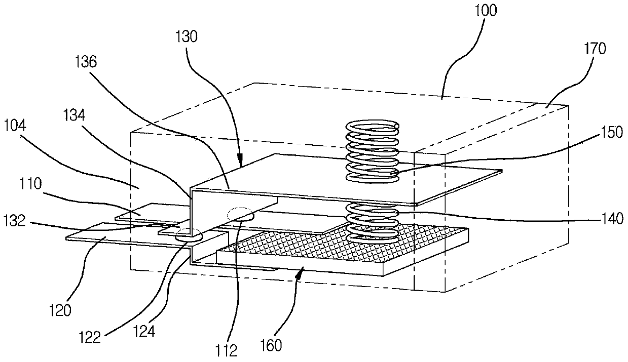
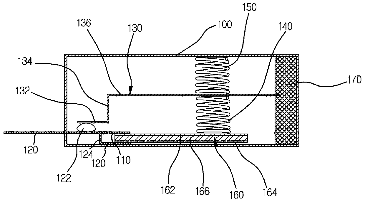
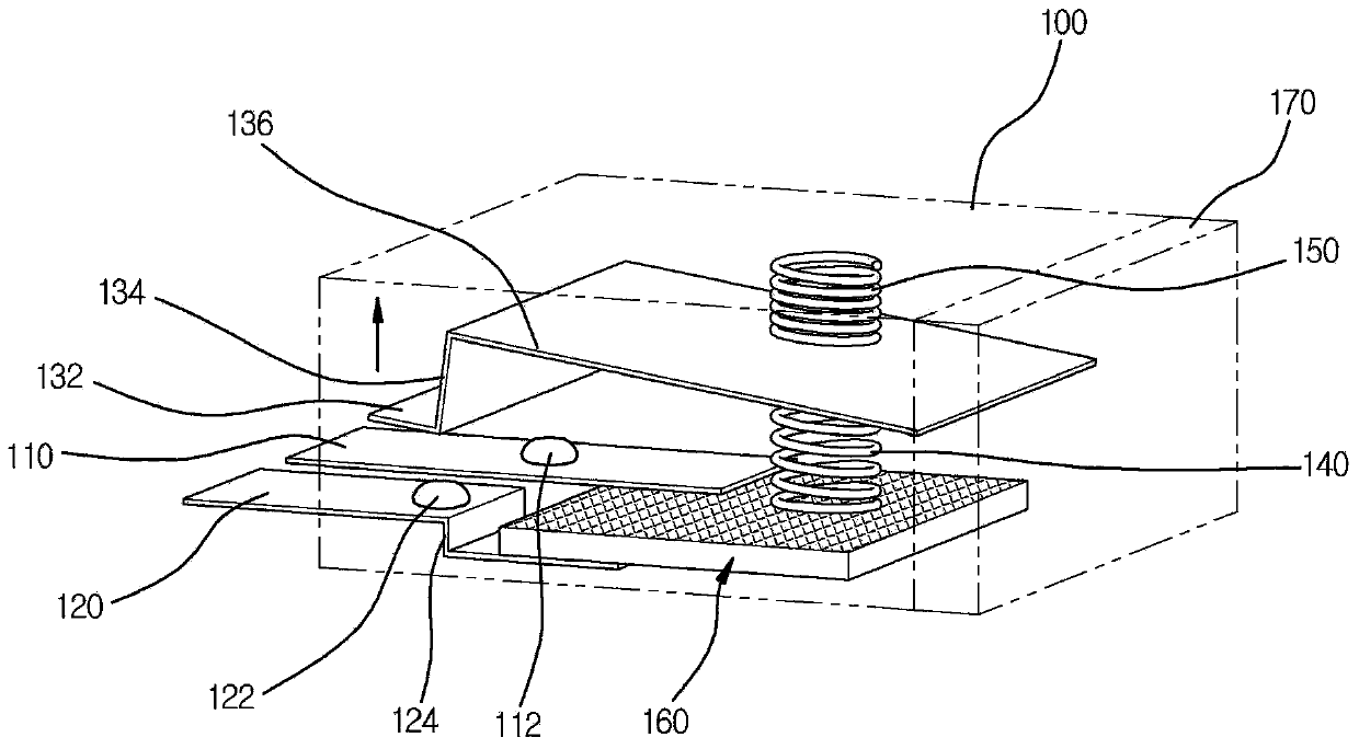
[0104] figure 1 A diagram schematically showing a self-resetting fuse for large current according to a first embodiment of the present invention, figure 2 for schematic representation figure 1 The cross-sectional view of a self-resetting fuse for high current, image 3 for expressing in figure 1 A diagram of the situation where the first lead terminal and the second lead terminal are electrically disconnected in a self-resetting fuse for high current, Figure 4 is a diagram showing an example of a positive temperature coefficient thermistor (positive temperaturecoefficient thermistor), Figure 5 This is a graph showing the resistance characteristics of a positive temperature coefficient thermistor based on temperature.

[0105] refer to Figure 1 to Figure 5 , according to the first embodiment of the present invention, the self-resetting fuse for large current includes: a casing 100 having an inner space; a first lead terminal 110 disposed on a first side surface of the ...

Embodiment 2

[0151] Figure 6 is a diagram schematically showing a resettable fuse for large current according to the second embodiment, Figure 7 for schematic representation Figure 6 The cross-sectional view of a self-resetting fuse for high current, Figure 8 for expressing in Figure 6 A diagram of the situation where the first lead terminal and the second lead terminal of the high current self-resetting fuse are electrically disconnected. In the following examples, descriptions of parts that overlap with those described in Example 1 are omitted as much as possible.

[0152] refer to Figure 6 to Figure 8 The resettable fuse for large current includes a trigger terminal 180 disposed on the second side surface of the housing 100 . The trigger terminal 180 is positioned by being inserted through the second side of the case 100, and may be formed of a conductive material. The trigger terminal 180 is configured to be connected to the positive temperature coefficient thermistor 160 ,...

Embodiment 3

[0163] Figure 9 is a diagram schematically showing a resettable fuse for large current according to the third embodiment, Figure 10 for schematic representation Figure 9 A cross-sectional view of a self-resetting fuse for high current.

[0164] refer to Figure 9 to Figure 10 , in the self-resetting fuse for large current, the main spring 140 and the bias spring 150 are configured to be able to expand or compress in a direction parallel to the direction in which the connecting portion 132 of the contact operating plate 130 moves, and the main spring 140 is arranged between the positive temperature coefficient thermistor 160 and the first plate portion 136, and the bias spring 150 is arranged on the contact operation plate 130 on the opposite side to the side where the main spring 140 is arranged based on the first connecting portion 134. between the connecting portion 132 and the inner wall of the casing 100 . The connection part 132 of the contact operation plate 130 m...


PUM


Abstract

The present invention relates to a repeatable fuse for high current. The repeatable fuse includes: a housing provided with an inner space and a first lead terminal disposed on one side surface of the housing; a second lead terminal disposed on the side surface of the housing, wherein the second lead terminal is spaced from the first lead terminal; a movable contact plate disposed within the housing and electrically short-circuited with the housing, wherein the movable contact plate is electrically switched on-off with the first lead terminal or the first and second lead terminals; main and bias springs disposed within the housing, wherein the main and bias spring electrically switch on-off the first lead terminal and the movable contact plate or the first and second lead terminals and the movable contact plate; and a positive temperature coefficient thermistor inserted into the housing, wherein the positive temperature coefficient thermistor is electrically connected to the first and second lead terminals. The positive temperature coefficient thermistor includes a positive temperature coefficient device in which electric resistance increases at a temperature greater than a special critical temperature. The movable contact plate may be linked with the tension forces of the main spring and bias spring. That is, the movable contact plate may be linked to move in the direction in which the main spring and the bias spring are extended or compressed, thereby being electrically connected to or short-circuited with the first lead terminal or the first and second lead terminals.

Description

technical field [0001] The present invention relates to a large current self-resetting fuse with a positive temperature coefficient thermistor (positive temperature coefficient thermistor), in particular to a positive temperature coefficient thermal The resistance of the thermistor increases sharply and continues to limit the flow of current, so that the power supply can be continuously blocked, and when the overcurrent disappears or the external overheating cause disappears, the current that returns to the normal state as the positive temperature coefficient thermistor cools down Self-resetting fuses are used for large currents flowing. Background technique [0002] Generally, all electrical and electronic products that use electricity always have the possibility of accidents caused by abnormal overcurrent in the circuit or overheating caused by external overheating reasons. Conventionally, a disposable fuse made of a material that melts and cuts due to heat caused by the ...

Claims


Application Information

Patent Timeline
IPC IPC(8): H01H85/36H01C7/02
CPCH01C1/1406H01H37/765H01C7/02H01H85/36
Inventor 金德熙朴夏荣
Owner MS TECHVISION
Why Eureka
Try Eureka