Drying structure of water jet loom

A water jet loom and drying technology, which is applied in drying gas arrangement, progressive dryer, textile and other directions, can solve the problems of high energy consumption and insignificant drying effect.

Inactive Publication Date: 2014-08-13
SUZHOU DONGMAO TEXTILE IND
View PDF5 Cites 3 Cited by
  • Summary
  • Abstract
  • Description
  • Claims
  • Application Information

AI Technical Summary

Problems solved by technology

In the past, after the fabric was squeezed and dehydrated by the pressing roller and friction roller of the loom, a heat source or hot air was used to dry the fabric before it was wound up. However, the drying effect of this method is not obvious and the energy consumption is high.

Method used


Image

  • Drying structure of water jet loom

Examples


Embodiment Construction

[0013] Below in conjunction with accompanying drawing and embodiment the present invention is further described:

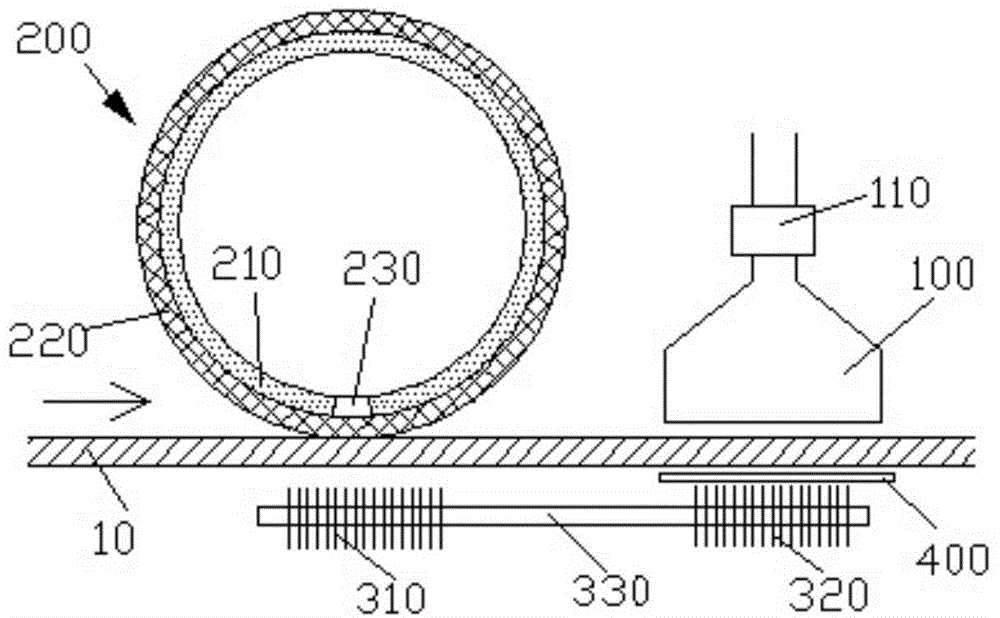
[0014] refer to figure 1 , in this embodiment, the drying structure of the water jet loom includes a heating roller 200 and a negative pressure cover 100 arranged in sequence in the direction of fabric 10 transmission, and the heating roller 200 and negative pressure cover 100 are perpendicular to the transmission of the fabric 10 direction, the heating roller 200 is made of thermally conductive material, the heating roller 200 is provided with a pressure relief member 230 , and the negative pressure cover 100 communicates with the heating roller 200 through an air pump 110 .

[0015] In the drying structure of the above-mentioned water jet loom, the other side of the negative pressure cover 100 relative to the fabric 10 is correspondingly provided with a filter screen 400 that restricts the passage of airflow, so that the negative pressure cover 100 receives air ...


PUM


Abstract

The invention provides a drying structure of a water jet loom. The drying structure of the water jet loom comprises a heating roller and a negative-pressure cover, which are orderly arranged in a fabric conveying direction; the heating roller and the negative-pressure cover are arranged perpendicular to the fabric conveying direction; the heating roller is made of a heat-conducting material; a pressure relief member is arranged on the heating roller; the negative-pressure cover is communicated with the heating roller by virtue of an air pump. Hot compressed air from the air pump in the drying structure of the water jet loom is used for heating the heating roller, the heating roller is used for heating the fabrics, and the moisture of the heated fabrics can be evaporated more quickly under the negative pressure of the negative-pressure cover.

Description

Technical field [0001] The invention relates to the field of loom equipment, in particular, a fabric drying structure for a water jet loom. Background technique [0002] The shuttleless loom is a new type of loom that was born after the shuttle loom. Shuttleless looms quickly occupied the loom market due to their light weight, low vibration, low noise, fast speed, and high efficiency. The water jet loom is a kind of shuttleless loom, which is a shuttleless loom that uses water jets to pull the weft through the shed. Water-jet weft insertion has greater friction and traction on weft yarn than air-jet weft insertion, and has less diffusivity, which is suitable for weft insertion of filaments such as synthetic fibers and glass fibers with smooth surfaces. At the same time, it can increase the conductivity of the synthetic fiber and effectively overcome the static electricity in weaving. In addition, jetting the weft yarn consumes less energy and produces the lowest noise lev...

Claims


Application Information

Patent Timeline
Patent Type & Authority Applications(China)
IPC IPC(8): D03J1/06F26B13/02F26B21/00F26B23/10
Inventor 钟钊伟
Owner SUZHOU DONGMAO TEXTILE IND
Why Eureka
Try Eureka