
A cam-driven axial piston pump with a rotating window for oil distribution

An axial piston pump and end face cam technology, which is applied to the components of the pumping device for elastic fluids, piston pumps, and variable displacement pump components, etc., can solve the problem of limited pump displacement, complex structure, and high processing costs. problems, to achieve the effect of improving reliability, simple transmission, and compact structure

Inactive Publication Date: 2016-03-02
XI AN JIAOTONG UNIV
View PDF9 Cites 0 Cited by
  • Summary
  • Abstract
  • Description
  • Claims
  • Application Information

AI Technical Summary

Problems solved by technology

Since the cylinder rotates together with the transmission shaft, the total moment of inertia of the pump is large, and the response speed of the pump's start-stop and speed regulation is slow, which is not conducive to directly adjusting the output flow of the pump by controlling the speed; since the oil rotates with the cylinder at high speed , cavitation and temperature rise are easy to occur inside the oil, which is not conducive to improving the volumetric efficiency and energy utilization rate of the pump; and there are many relatively moving parts in the pump body, resulting in a more complicated structure inside the pump, high processing costs and low reliability ; Since the movement of the plunger is realized by the angle between the plunger and the swash plate or the transmission shaft and the cylinder body, the plunger can only complete one oil suction and oil pressure action when the transmission shaft rotates one revolution, so the discharge of the pump In addition, the oil inlet and outlet of the common axial piston pump are generally located on the side of the pump body, and usually need pipelines to connect with the external oil circuit, which is not easy to realize the integration of the pump and other components

Method used


Image

  • A cam-driven axial piston pump with a rotating window for oil distribution
  • A cam-driven axial piston pump with a rotating window for oil distribution
  • A cam-driven axial piston pump with a rotating window for oil distribution

Examples


Embodiment Construction

[0024] The present invention will be described in detail below in conjunction with the accompanying drawings.

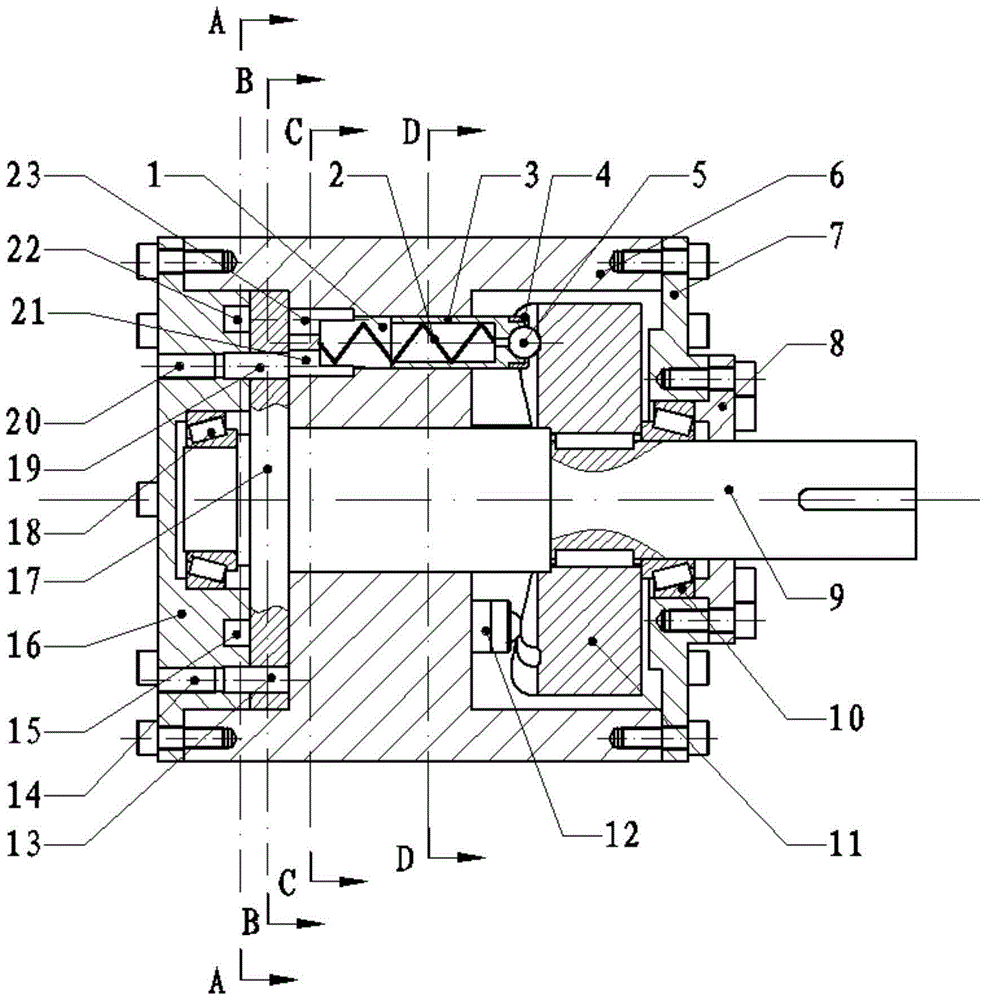
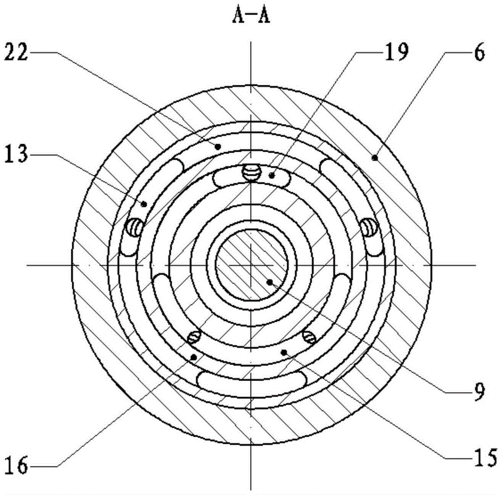
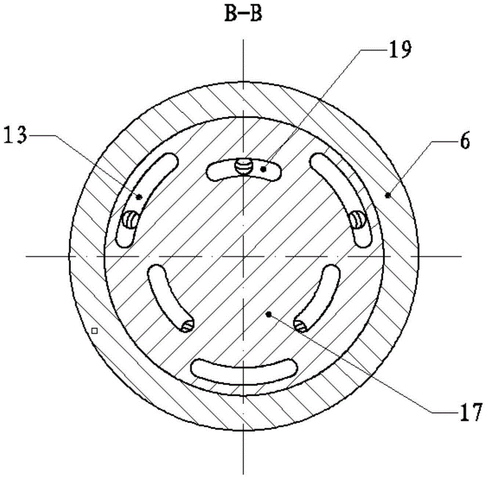
[0025] refer to figure 1 , figure 2 , image 3 , Figure 4 with Figure 5 , an end face cam-driven axial piston pump that uses a rotating window to distribute oil, including an integral pump body 6, a first pump end cover 16 and a second pump end cover 7 fixedly installed on both ends of the integral pump body 6 side, the transmission shaft 9 is installed inside the integrated pump body 6, and is supported on the first pump end cover 16 and the second pump end cover 7 through the first rolling bearing 18 and the second rolling bearing 10 respectively, and the axis of the transmission shaft 9 The extension end is on the side of the second pump end cover 7, and the driving cam 11 is installed on the transmission shaft 9, and is fixed with the transmission shaft 9 through a key connection, and the shoulder on the driving cam 11 is pressed against the shoulder of th...


PUM


Abstract

The invention relates to an end cam driving type axial plunger pump adopting rotating window oil distribution. An integrated pump body structure is adopted, and a cylinder body in a traditional axial plunger pump is combined with a shell; through flow distribution of a rotating window flow distribution disc on a transmission shaft, an integrated pump body is fixed, a plunger group mounted at the interior of the integrated pump body does not rotate along with the transmission shaft, the plunger group in the pump moves in a reciprocating manner under the effect of a driving cam, a total oil inlet and a total oil outlet of the pump are formed in the ends and can be in straight-through joint with other hydraulic components, and the connection is simple and convenient; moreover, a first pump end cover in the pump and a part of the other hydraulic components can be made into one body, and thus the integrated design of the pump and the hydraulic pumps is realized; the end cam driving type axial plunger pump has the advantages of compact structure, simple transmission, small rotational inertia, high rotating speed, large discharge capacity and capability of being directly connected with the other hydraulic components.

Description

technical field [0001] The invention belongs to the technical field of axial plunger pumps, and in particular relates to an end face cam-driven axial plunger pump adopting a rotating window for oil distribution. Background technique [0002] Axial piston pump is the most commonly used pressure oil source in engineering hydraulic systems. It has the advantages of simple structure, small size, low noise, high efficiency, and self-priming ability. It is widely used in forging, metallurgy, shipbuilding and other fields. in the hydraulic system. [0003] The working principle of the traditional axial piston pump is: the transmission shaft directly or indirectly drives the cylinder to rotate, and the rotation of the transmission shaft is converted into the reciprocation of the plunger through the angle between the plunger and the swash plate or the transmission shaft and the cylinder. Movement, thereby periodically changing the volume of the plunger chamber, to achieve the action...

Claims


Application Information

Patent Timeline
Patent Type & Authority Patents(China)
IPC IPC(8): F04B9/04F04B53/16
Inventor 赵升吨郭桐刘辰韩晓兰张晨阳李靖祥张琦
Owner XI AN JIAOTONG UNIV
Learn More