Novel composite pipe compensator

A pipeline compensator and composite technology are applied in the field of thermal pipeline compensator and thermal pipeline compensator structure, which can solve the problems of increasing fluid medium pressure loss, increasing pipeline network cost and pressure loss, and high cost, and reducing pipeline stress. , Improve the pressure bearing capacity, the effect of safe and reliable operation

Active Publication Date: 2014-08-13
陈墅庚
View PDF4 Cites 6 Cited by
  • Summary
  • Abstract
  • Description
  • Claims
  • Application Information

AI Technical Summary

Problems solved by technology

Among them: the cost of the spherical compensator is too high, while the performance of the domestically produced spherical compensator is average, and the pressure loss is large; the corrugated compensator has too much stress in the pipeline in practical application, and there is always a safety hazard in the pipeline operation; and the original Π-shaped compensator is used. The investment and pressure loss of the natural compensation method are the same; the structure and sealing performance of the existing sleeve compensator are not good, the leakage phenomenon is common, and the anti-corrosion link is also relatively weak; the performance of the rotary compensator is better; Large, flexible layout, especially in long-distance overhead pipelines, the application advantages are obvious; but there are also shortcomings: First, the gap between the joint part of the inner pipe and the reducing pipe is too large, and there will be problems in this part during the movement of the fluid medium. Vortex, which increases the pressure loss of the fluid medium
Second, because the structure of the rotary compensator is a radial working principle, it must occupy a certain space when it is applied in the pipeline; and each set of compensator installation points must be equipped with a drain valve; this increases the cost and pressure loss of the pipeline network; Especially in buried pipelines, it cannot be widely used; especially, the existing spherical compensators, sleeve compensators, corrugated compensators, and rotary compensators all adopt a single sealing form. In terms of use: fluid medium and pressure bearing capacity are subject to certain limitations

Method used


Image

  • Novel composite pipe compensator
  • Novel composite pipe compensator

Examples


Embodiment Construction

[0045] The technical solutions of the present invention are described in detail below in conjunction with the accompanying drawings.

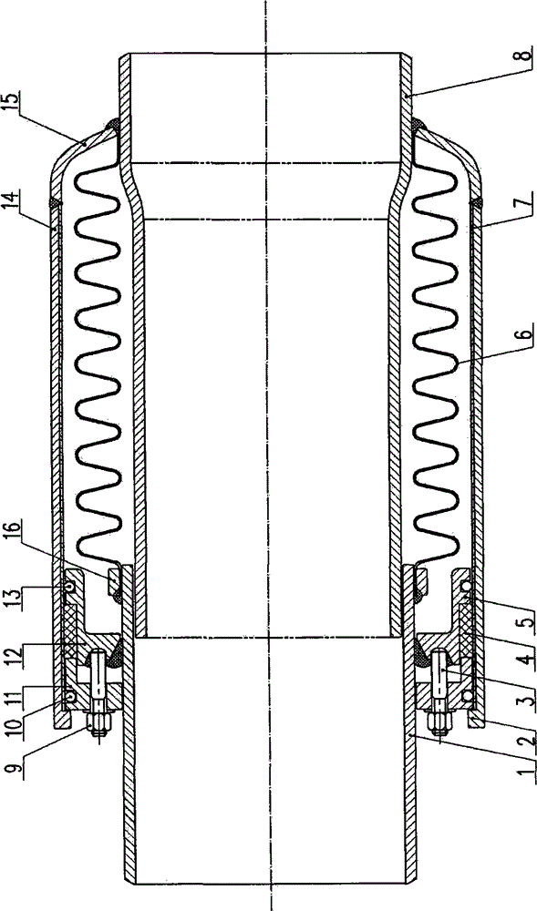
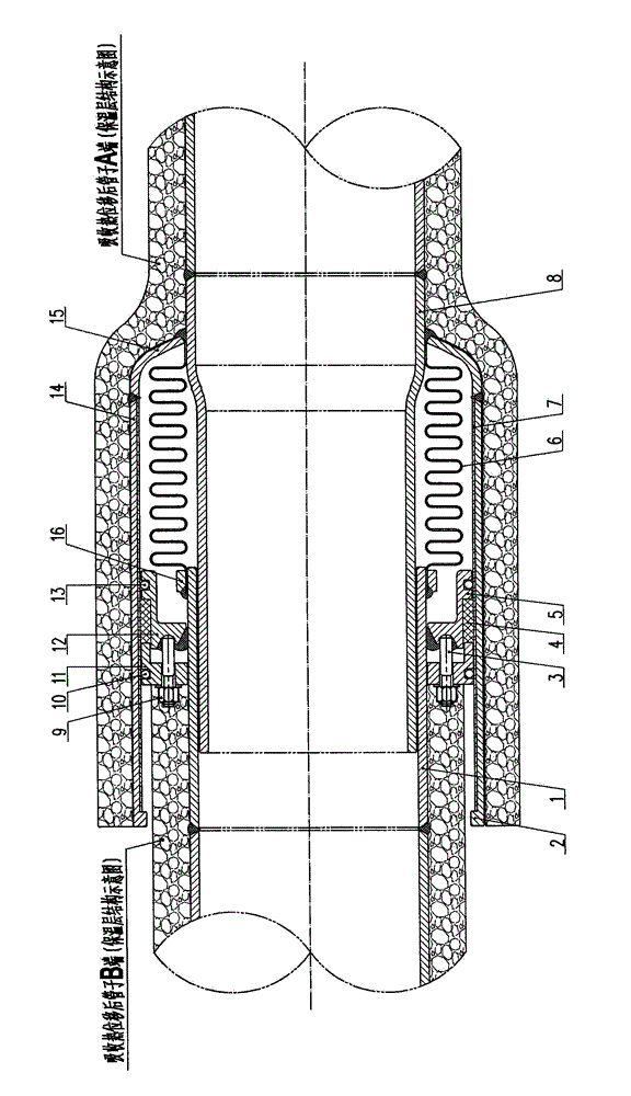
[0046] Such as figure 1 and figure 2 shown. A new type composite pipeline compensator, including: tube B1, pull-off stop ring 2, countersunk bolt 3, seal 4, seal seat 5, bellows 6, anti-corrosion lining 7, tube A8, nut 9 , steel ball A10, seal gland flange 11, seal structure 12, steel ball B13, outer casing 14, outer casing head 15 and pressure ring 16;

[0047] Both the pipe A8 and the pipe B1 have a structure in which the pipe A8 is coaxially inserted into the pipe B1;

[0048] The pipe A8 is a cylindrical one-piece variable-diameter tube structure, that is, the tube A8 is an integrated tube structure with an inner diameter at one end greater than the inner diameter at the other end. Reduced diameter end, a structure in which the reduced diameter end and the non-reduced diameter end are connected through a transition arc (reduced diamete...


PUM


Abstract

The invention discloses a novel composite pipe compensator and belongs to the technical field of heat distribution pipe compensation devices. The novel composite pipe compensator is characterized in that an outer sleeve seal head is arranged on an outer ring of a pipe A, a pipe B is coaxially and annularly sheathed on the outer ring at one end of the pipe A, a corrugated pipe is annularly sheathed on the surface of the outer ring of the pipe A, and the two ends of the corrugated pipe are respectively, tightly and fixedly connected with the pipe A and the pipe B; an outer sleeve is arranged on the outer side of a sealing seat to form a structure that the outer sleeve seal head which is integrally arranged on the outer ring of the pipe A and one end, including the corrugated pipe, of the outer pipe sleeve are of an integrated structure and can coaxially, synchronously and integrally move under the squeezing and pushing effect of axial thermal expansion force. By adopting the structure, the novel composite pipe compensator has the advantages that the pipe stress is reduced, the sealing performance is enhanced, the pressure bearing capacity is improved, large compensation can be realized and the application scope is wide.

Description

technical field [0001] The invention relates to a novel composite pipeline compensator, which belongs to the technical field of thermal pipeline compensation devices, and specifically belongs to the technical field of thermal pipeline compensation device structures used in industries such as petroleum, chemical industry, light industry, thermal power, and metallurgy. Background technique [0002] Common pipeline compensation methods in the prior art are as follows: 1. Traditional natural U-bend type, 2. Spherical compensator, 3. Sleeve compensator, 4. Corrugated compensator, 5. Rotary compensator. Among them: the cost of the spherical compensator is too high, while the performance of the domestically produced spherical compensator is average, and the pressure loss is large; the corrugated compensator has too much stress in the pipeline in practical application, and there is always a safety hazard in the pipeline operation; and the original Π-shaped compensator is used. The i...

Claims


Application Information

Patent Timeline
Patent Type & Authority Applications(China)
IPC IPC(8): F16L51/02F16L58/02
CPCF16L51/025F16L58/18
Inventor 陈墅庚马洪波夏孝刚陈振兴
Owner 陈墅庚
Why Eureka
Try Eureka