Two-stage precooling dehumidification device and method

A pre-cooling and evaporative technology, applied in the field of air-conditioning equipment, can solve the problems of insignificant energy saving effect, large energy consumption, and small air volume, and achieve the effect of increasing the dehumidification per unit input power, reducing redundant devices, and improving the energy efficiency of the whole machine

Inactive Publication Date: 2014-08-13
NANJING NORMAL UNIVERSITY
View PDF6 Cites 25 Cited by
  • Summary
  • Abstract
  • Description
  • Claims
  • Application Information

AI Technical Summary

Problems solved by technology

However, most of the existing dehumidification systems not only cannot meet people's needs, but also consume a lot of energy.
For example, most of the dehumidification systems in China today adopt the form of fresh air. The unit under this design has the characteristics of small air volume and large enthal

Method used


Image

  • Two-stage precooling dehumidification device and method
  • Two-stage precooling dehumidification device and method

Examples


Embodiment Construction

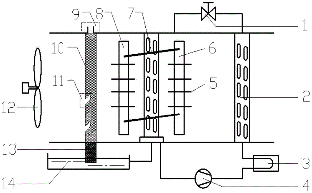
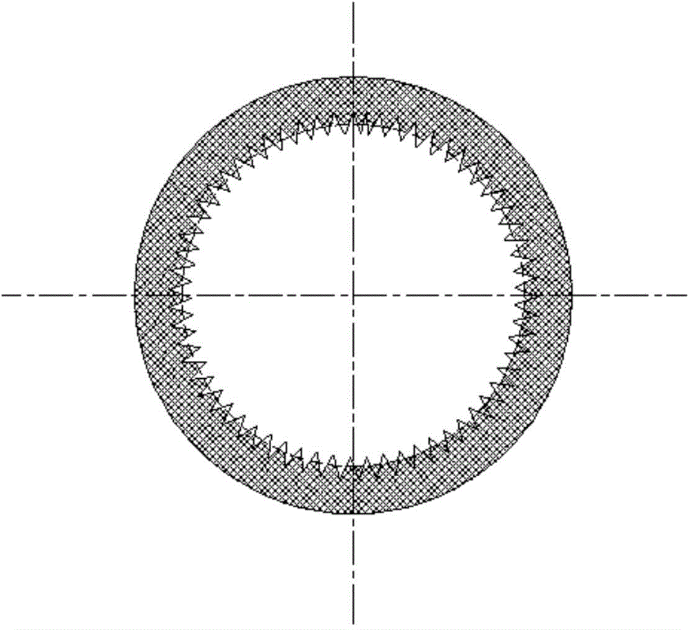
[0018] As shown in the figure, 1 is the throttling device of the refrigeration system, 2 is the air-cooled condenser of the refrigeration system, 3 is the water-cooled condenser, 4 is the compressor, 5 is the fin, 6 is the two-phase closed thermosiphon condensing section, 7 evaporator (surface cooler) of the refrigeration system, 8 two-phase closed thermosiphon evaporating section, 9 is the air outlet, 10 is the indirect evaporative circular tube surface heat exchanger, 11 is the variable-section nozzle, 12 is the induced draft fan, 13 is the near-ground end of the round pipe (filled with porous material), and 14 is the condensation water tank. The heat pipe device adopts a two-phase closed thermosiphon, which includes a heat pipe evaporation section, a condensation section and two working fluid circulation channels. The evaporation and condensation of the working fluid are used to transfer heat, and the working fluid circulates automatically without external power.

[0019] ...


PUM


Abstract

The invention discloses a two-stage precooling dehumidification device and method, which break through a traditional dehumidification system form. The two-stage pre-cooling dehumidification device comprises an indirect evaporative circular tube surface heat exchanger, a heat pipe heat exchanger, a refrigeration dehumidification system and a condensed water collecting device, all of which sequentially form a primary fresh air precooling section, a secondary precooling section, a dehumidification section and a coolant recovery section. According to the two-stage precooling dehumidification device and method, cooling capacity of high-graded exhaust air and condensed water is sufficiently used for precooling fresh air, so that the cooling load of an evaporator of a dehumidification unit is reduced, and thus the unit input power can be less when the unit achieves the same dehumidification workload. Therefore, economic and better selection can be realized on accessory model selection of the unit.

Description

technical field [0001] The invention belongs to the technical field of air conditioners, and relates to a two-stage precooling dehumidification unit and a dehumidification method. Background technique [0002] With the continuous improvement of people's living standards, people pay more and more attention to indoor air quality, which is manifested in higher and higher requirements for suitable air temperature and humidity, especially in the south. There is a strong sense of discomfort. However, most of the existing dehumidification systems not only cannot meet people's needs, but also consume a lot of energy. For example, most of the dehumidification systems in China today adopt the form of fresh air. The unit under this design has the characteristics of small air volume and large enthalpy difference. Its structure is complex and bulky. The application value in the market is not high, and the energy-saving effect is not obvious. , and condensed water continues to be genera...

Claims


Application Information

Patent Timeline
IPC IPC(8): F24F3/14F24F12/00F24F13/30
Inventor 王若琳纪鹏越赵孝保
Owner NANJING NORMAL UNIVERSITY
Why Eureka
Try Eureka