Effect-enhanced serial nozzle two-phase flow ejector and component refrigerating system thereof

An ejector and tandem technology, used in refrigerators, refrigeration components, refrigeration and liquefaction, etc., can solve the problem of performance improvement that has not been reported in depth, the speed difference between vapor and liquid phase is large, fluid vapor, liquid Due to the large difference in phase density and other problems, the effects of easy processing and popularization and application, high ejection efficiency and no moving parts are achieved.

Inactive Publication Date: 2014-08-13
TIANJIN UNIV OF COMMERCE
View PDF4 Cites 4 Cited by
  • Summary
  • Abstract
  • Description
  • Claims
  • Application Information

AI Technical Summary

Problems solved by technology

[0003] However, in the vapor compression refrigeration cycle, the working medium in the ejector presents a two-phase flow, and the density difference between the fluid vapor and liquid phases is very large. The phase separation of the working medium in the ejector is very serious, and the speed difference between the vapor and liquid phases is very large, which greatly affects the actual ejection efficiency of the nozzle, thereby affecting the performance of the refrigeration equipment
[0004] In order to solve the problem of low injection efficiency of single-stage scaling nozzles, many researchers at home and abroad have proposed corresponding technical solutions, such as: predicting system performance through numerical simulation of steam injection refrigeration cycle, and exploring the optimal size of ejector , or by studying the influence of condensing temperature and ejection fluid temperature to find out the relationship between working conditions and the performance of the refrigeration cycle system, etc.
[0005] However, at present, all kinds of research work are aimed at the refrigeration system of single-stage scaling nozzle ejector, and there is no substantial change to the ejector, and the specific performance improvement status has not been reported in depth, and the improvement measures are subject to various Influenced by factors, the difficulty of control increases significantly

Method used


Image

  • Effect-enhanced serial nozzle two-phase flow ejector and component refrigerating system thereof
  • Effect-enhanced serial nozzle two-phase flow ejector and component refrigerating system thereof
  • Effect-enhanced serial nozzle two-phase flow ejector and component refrigerating system thereof

Examples


Embodiment Construction

[0021] The present invention will be described in further detail below in conjunction with the accompanying drawings and specific embodiments.

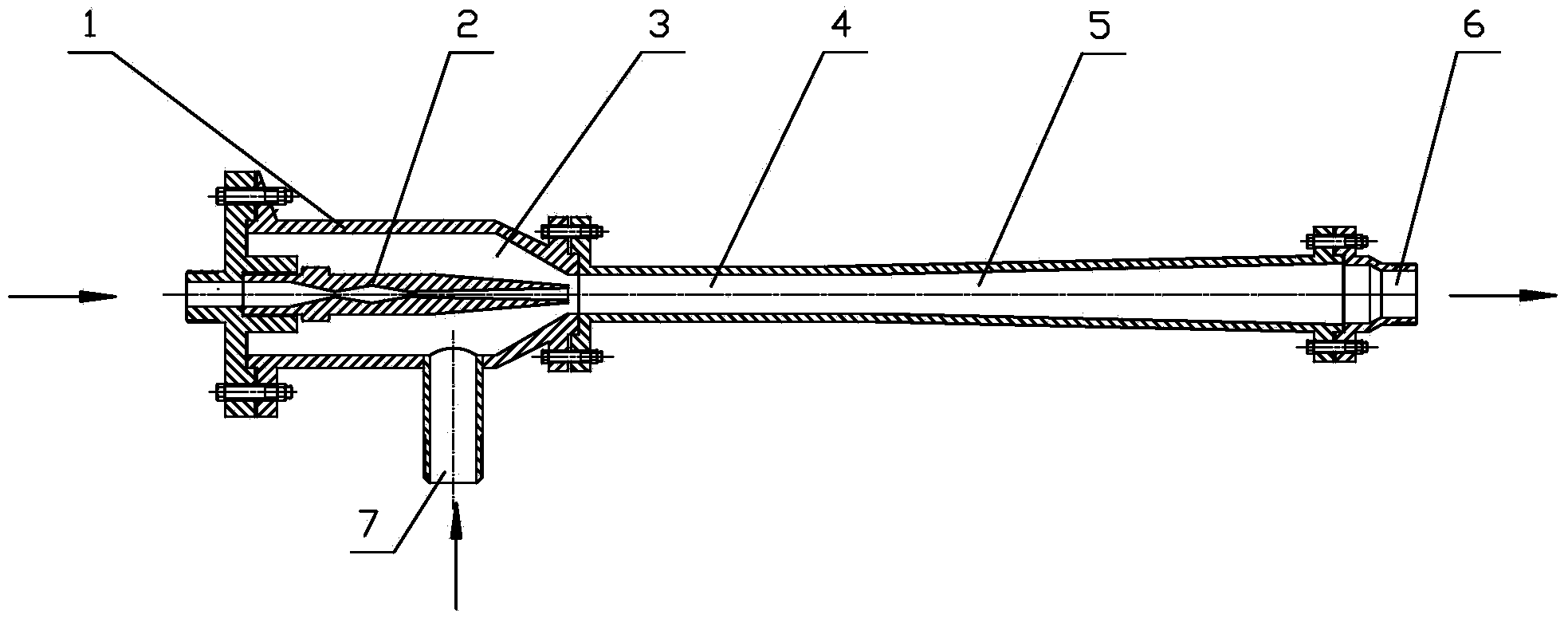
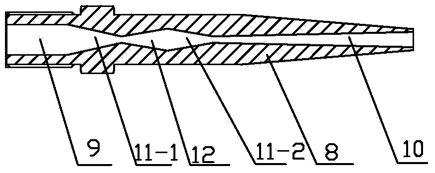
[0022] The schematic diagram of the synergistic tandem nozzle two-phase flow ejector of the present invention is as follows figure 1 with figure 2 As shown, it includes an ejector housing 1, an injection structure 2, a receiving chamber 3, a mixing chamber 4, a diffuser chamber 5 and an ejector outlet part 6, and the ejector housing 1 is provided with a main ejector inlet ( figure 1 at the left arrow in the middle) and the induced jet flow inlet 7. The injection structure 2 is installed inside the ejector housing 1, and the injection structure 2 includes an injection body 8. One end of the injection body 8 is an injection inlet port 9, and the other end is an injection outlet port 10. The inlet port 9 is connected to the main jet inlet, the main jet inlet port and the jet inlet port 9 are cylindrical flow channels, and the jet inle...


PUM


Abstract

The invention discloses an effect-enhanced serial nozzle two-phase flow ejector and a component refrigerating system thereof and aims to improve ejecting efficiency. An ejecting structure is mounted inside an ejector shell and comprises an ejector body, at least two sections of nozzles are serially connected between an ejection inlet end and an ejection outlet end of the ejecting structure, expanding sections are arranged between every two adjacent sections of nozzles, a receiving chamber is formed between the inner wall of the ejector shell and the ejector body, and a mixing chamber and a diffusion chamber are sequentially arranged between the ejection outlet end a eject flow outlet part. Refrigerant is accelerated since pressure in the first section of nozzle is converted into kinetic energy and then is decelerated after flowing to the expansion section; the refrigerant flows to the next section of nozzle to be subjected to acceleration and pressurization for twice or multiple times before entering the mixing chamber and the diffusion chamber together with a eject flow, and finally flows out from the eject flow outlet part; since the refrigerant is close to a homogeneous flow state, an eject ratio and energy efficiency of the refrigerating system are improved.

Description

technical field [0001] The invention relates to a synergistic tandem nozzle two-phase flow ejector and a refrigeration system composed of the two-phase flow ejector. Background technique [0002] In the two-phase flow refrigeration cycle system, recovering a part of the pressure energy of the high-pressure working medium can greatly improve the coefficient of performance (COP) of the refrigeration system. At present, there are two main methods: one is to use the expander to replace the throttle valve. The advantage of this solution is that the energy recovery efficiency is high, but there are problems such as the complex structure of the expander and the high cost, and the expander mainly works in the two-phase region. , the fluid-filled expansion has a great impact on its working reliability, and there are still many technical problems to be solved. Another method uses the ejector as a booster pump to convert the expansion work of the high-pressure working medium into kine...

Claims


Application Information

Patent Timeline
Patent Type & Authority Applications(China)
IPC IPC(8): F25B41/00F25B31/00
Inventor 郭宪民汪伟华任立乾
Owner TIANJIN UNIV OF COMMERCE
Why Eureka
Try Eureka