

Annular sintering machine for water seal
A sintering machine and water sealing technology, which is applied in the direction of furnace, furnace type, lighting and heating equipment, etc., can solve the problems of heavy rotating weight, high pressure bearing requirements, complex mechanism, etc., achieve low equipment cost, reduce air leakage points, improve The effect of the operating environment
- Summary
- Abstract
- Description
- Claims
- Application Information
AI Technical Summary
Problems solved by technology
Method used
Image

Examples
Embodiment 1
[0090] Example 1, such as Figure 1~Figure 9 shown.
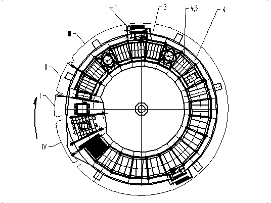
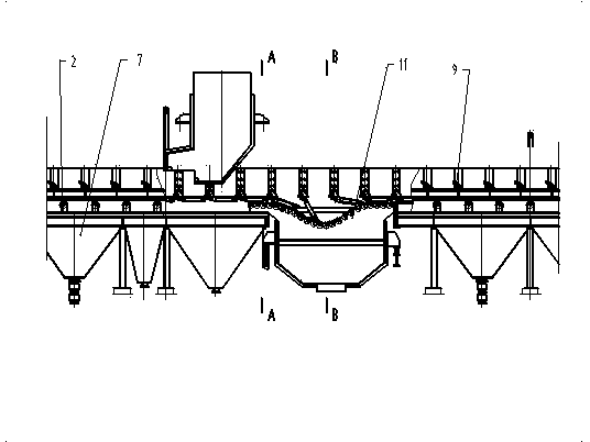
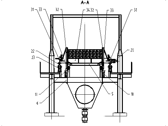
[0091] The water-sealed annular sintering machine consists of a transmission device 1, a traveling device 2, a revolving body 3 (the inner and outer revolving frames 31, the inner and outer fences 32, and connecting beams 34 together constitute the revolving body 3), grate bars 4, support frames 5, and support Platform 6, bellows 7 etc. are formed. The revolving body 3 is driven by the transmission device 1 to rotate around the same center.
[0092] The grate bar 4 is installed on the support frame 5, and the support frame 5 is hinged to the lower part of the connecting beam 34; the water-sealed annular sintering machine is divided into a material distribution area I, an ignition area II, a sintering work area III and a discharge area IV, at the beginning of the work area , the support frame 5 is locked by the locking device 9. In the material distribution area, the mixed material is unloaded onto the support frame 5 and ...
Embodiment 2
[0098] Example 2, such as Figure 10~Figure 16 shown.
[0099] This embodiment is a change carried out on the basis of Embodiment 1, and its main difference with Embodiment 1 is:
[0100] First, the running device 2 is made up of the inner track 21, the outer track 22 and the wheels 23; the wheels 23 are fixed on the bottom of the revolving frame 31 and rotate with the revolving body 3; the inner track 21 and the outer track 22 are fixed on the support platform 6; The inner and outer rails 21, 22 move, and the inner and outer rails 21, 22 support the rotary body 3 and the weight of the material through the wheels 23. ,
[0101] Second, the guiding device 11 in the unloading area is a curved rail, located at the bottom of the support frame 5 in the unloading area, and within the scope of the support frame 5, the shape is a continuous irregular concave shape, and the lower end of the support frame 5 has increased scroll wheel.
[0102]The 3rd, locking device is cam locking d...
Embodiment 3
[0104] Example 3, such as Figure 16 shown.
[0105] This embodiment is a change carried out on the basis of Embodiment 1. Its main difference from Embodiment 1 is that the sealing plate 33 is removed, and the upper end of the water sealing knife 105 of the annular continuous water sealing device 10 is connected to the fence. 32, the rest of the content is the same as in Embodiment 1, which can be interpreted from the relevant description of Embodiment 1.
PUM
 Abstract
Description
Claims
Application Information