Visual online image ferrography imaging system

An imaging system and ferrography technology, applied in the direction of measuring devices, material analysis through optical means, instruments, etc., can solve problems such as uneven illumination, limited imaging range, and difficulty in extracting wear particle feature information, so as to enhance the acquisition ability, Effects of improving image quality and increasing illumination range

Inactive Publication Date: 2014-08-13
XI AN JIAOTONG UNIV
View PDF9 Cites 35 Cited by
  • Summary
  • Abstract
  • Description
  • Claims
  • Application Information

AI Technical Summary

Problems solved by technology

The patents "online digital image type electromagnetic permanent magnet hybrid excitation magnetogram sensor (200510041894.X)" and "short deposition distance image type online ferrography device and method (200610041773.X)" have realized the online monitoring of abrasive particles equipped with lubricating oil However, due to the limitation of the installation space, the magnification of the imaging device changes due to the error of the lens focal length, resulting in blurred imaging. At the same time, the light intensity of the reflected light source and the transmitted light source are low, and the illumination is uneven, which affects the iron. Clarity of Spectral Imaging
In addition, since the transmitted light source is installed directly under the working air gap of the deposition poles, the imaging range of the ferrogram image under transmitted light is limited, so that it can only obtain the wear particle ferrography image information in the main working air gap between the deposition poles, while The image information of abrasive particles in the opaque areas of the deposited magnetic poles on both sides of the air gap cannot be obtained
Therefore, the existing online image visual ferrography imaging range is small and the quality is poor, which makes image processing difficult and the extraction of wear particle feature information is difficult, which affects the accuracy of wear particle percentage coverage area index (IPCA) calculation and wear state monitoring. sex and reliability

Method used


Image

  • Visual online image ferrography imaging system
  • Visual online image ferrography imaging system
  • Visual online image ferrography imaging system

Examples


Embodiment Construction

[0021] The present invention is described in further detail below in conjunction with accompanying drawing:

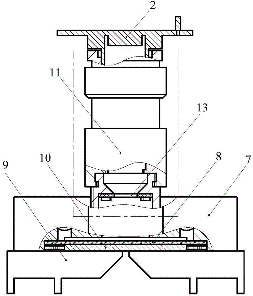
[0022] refer to figure 1 , the online image visible ferrography imaging system of the present invention comprises image acquisition device 2, lens seat, focusing mechanism 11, LED annular reflective light source 13 and two-color ultra-thin LED backlight source 10, and image acquisition device 2 passes lens seat cover Connected and fixed on the upper part of the focusing mechanism 11, the bottom of the focusing mechanism 11 is connected with the oil flow channel 7 in the ferrogram through threads, and the LED ring-shaped reflective light source 13 is fixedly connected with the threaded lens barrel 5 in the focusing mechanism 11, two-color The ultra-thin LED backlight source 10 is bonded to the deposited glass slide 8 of the oil flow channel 7 in the ferrogram.

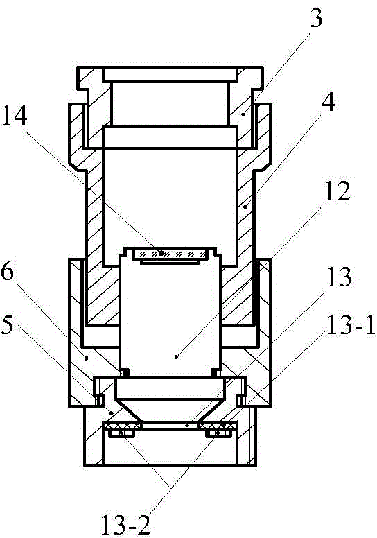
[0023] refer to figure 2 , it should be noted that the image acquisition device 2 is an M12 interface CCD ...


PUM


Abstract

The invention discloses a visual online image ferrography imaging system, which comprises an image acquisition device, a lens base, a focusing mechanism, an LED (Light Emitting Diode) annular reflection light source and a bicolourable ultra-thin LED backlight source; the image acquisition device is sleeved and fixed at the upper part of the focusing mechanism through the lens base; the bottom of the focusing mechanism is connected with an oil flow channel in ferrography through a thread; the LED annular reflection light source is fixedly connected with a threaded lens cone in the focusing mechanism; the bicolourable ultra-thin LED backlight source is adhered to a sedimentary slide in the oil flow channel in the ferrography. According to the invention, the object distance and the image distance are respectively adjusted through the focusing mechanism; the focal distance error of the lens is corrected; ferrography imaging with the fixed rate of 1.8 times can be realized; simultaneously, high-brightness and uniform illumination can be provided by adopting the LED annular reflection light source; the bicolourable ultra-thin LED backlight source as the transmission light source is wide in illumination range; the full-field ferrography imaging can be realized; the visual online image ferrography imaging system disclosed by the invention has the characteristics of being small in volume, high in imaging quality and easy for extracting visual abrasive particle characteristic information.

Description

technical field [0001] The invention relates to an imaging system of an equipment wear particle monitoring device, in particular to an online image visual ferrography imaging system. Background technique [0002] Ferrography technology conducts orderly deposition and analysis of ferromagnetic abrasive particles in the lubricating oil in use, monitors the operation status and wear trend of the equipment, judges the wear mechanism, realizes early failure prevention of equipment, reduces failure losses, and has stable performance, Reliable, strong anti-interference ability and many other advantages. Ferrography oil monitoring technology is divided into offline ferrography and online ferrography monitoring technology. Off-line ferrography analysis is a non-real-time monitoring method. It is necessary to send the lubricating oil of the equipment to the laboratory, and use the analytical ferrography instrument to make a spectrogram Manual analysis under a ferrographic microscope,...

Claims


Application Information

Patent Timeline
Patent Type & Authority Applications(China)
IPC IPC(8): G01N15/00G01N21/84
CPCG01N15/0205G01N15/1436G01N15/1459G01N15/147G01N21/85G01N33/2858G01N2015/0019G01N2015/144G01N2015/1452G01N2015/1493
Inventor 毛军红李博谢友柏
Owner XI AN JIAOTONG UNIV
Why Eureka
Try Eureka