Vehicle-mounted ranging laser radar system
A laser radar and radar system technology, applied in the field of vehicle radar, can solve the problems of high cost of scanning mirror system, restricting the popularization of vehicle ranging laser radar, etc., and achieve the effect of easy installation, small size and lower system cost.
- Summary
- Abstract
- Description
- Claims
- Application Information
AI Technical Summary
Problems solved by technology
Method used
Image

Examples
Embodiment Construction
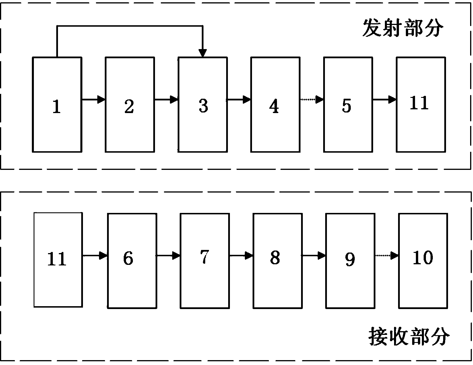
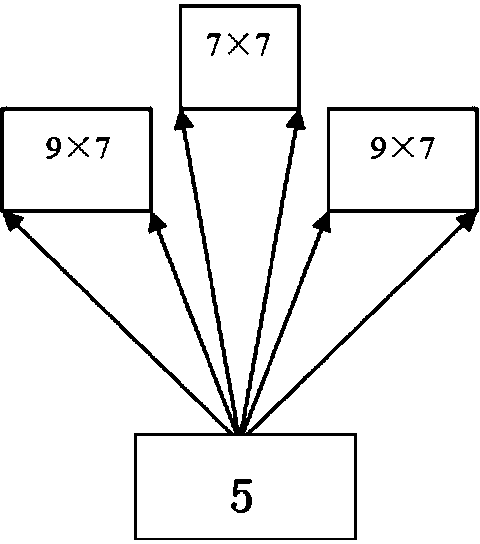
[0018] Such as Figure 1-4 As shown, the present invention is divided into a transmitting part and a receiving part, and the transmitting part includes: a power supply module 1 , a single-chip microcomputer 2 , a transmitting circuit 3 , a transmitting diode 4 and a diffraction grating 5 . The power supply module 1 supplies power for the entire system, the single-chip microcomputer 2 sends pulses to the transmitting circuit 3, and the transmitting circuit 3 sends high-power narrow pulses to the transmitting diode 4, and the transmitting diode 4 emits laser light. After passing through the diffraction grating 5, it is divided into three beams of light waves, covering the front three-dimensional area.
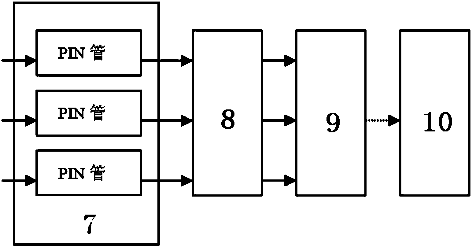
[0019] The receiving part includes: a receiving lens 6 , a PIN tube group 7 , a signal processing circuit 8 , a multiplexer 9 , and a timing chip 10 . When the target object 11 is encountered in the area, part of the reflected laser light is transmitted to the PIN tube group 7 t...
PUM
 Abstract
Description
Claims
Application Information
 - Generate Ideas
- Intellectual Property
- Life Sciences
- Materials
- Tech Scout
- Unparalleled Data Quality
- Higher Quality Content
- 60% Fewer Hallucinations
Browse by: Latest US Patents, China's latest patents, Technical Efficacy Thesaurus, Application Domain, Technology Topic, Popular Technical Reports.
© 2025 PatSnap. All rights reserved.Legal|Privacy policy|Modern Slavery Act Transparency Statement|Sitemap|About US| Contact US: help@patsnap.com