Distribution method capable of restraining grating lobes of large-space phased-array antenna

A phased array antenna and a large-spacing technology, which can be used in the fields of communication and navigation, can solve overlapping; in 2002, MarkL.Goldstein et al. applied for their patent, the complexity of other parts of the array, and the difficulty of manufacturing and processing the array, etc. Problems, achieve the effect of reducing design burden, reducing design difficulty, and reducing weight

Inactive Publication Date: 2014-08-13
LINGBAYI ELECTRONICS GRP
View PDF7 Cites 53 Cited by
  • Summary
  • Abstract
  • Description
  • Claims
  • Application Information

AI Technical Summary

Problems solved by technology

The second type of array does not need to constrain the antenna elements on an equally spaced regular grid like the first type of array, so the degree of freedom for optimization is greater, which is conducive to improving the correlation performance of the array antenna to a greater extent. There will be grating lobes, and the grating lobe level can be made very low, but this kind of array will increase the difficulty of manufacturing and processing the array, and make other parts of the array very complicated
[0011] Adjacent arrangement of equal-sized sub-arrays will lead to large grating lobes in the antenna pattern. For this reason, scholars at home and abroad have proposed a method of arranging multiple sub-arrays, such as: rotating sub-arrays. In 1978, Vishwani D .Agrawal and Thomas C.Tong obtained the effect of suppressing grating lobes by using an array compo

Method used


Image

  • Distribution method capable of restraining grating lobes of large-space phased-array antenna
  • Distribution method capable of restraining grating lobes of large-space phased-array antenna
  • Distribution method capable of restraining grating lobes of large-space phased-array antenna

Examples


Embodiment Construction

[0024] The present invention will be further described below in conjunction with the accompanying drawings.

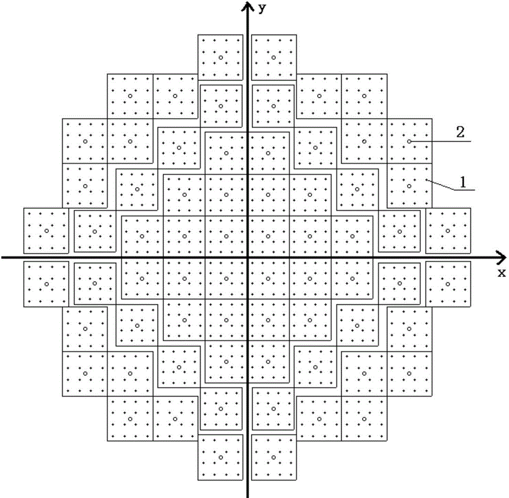
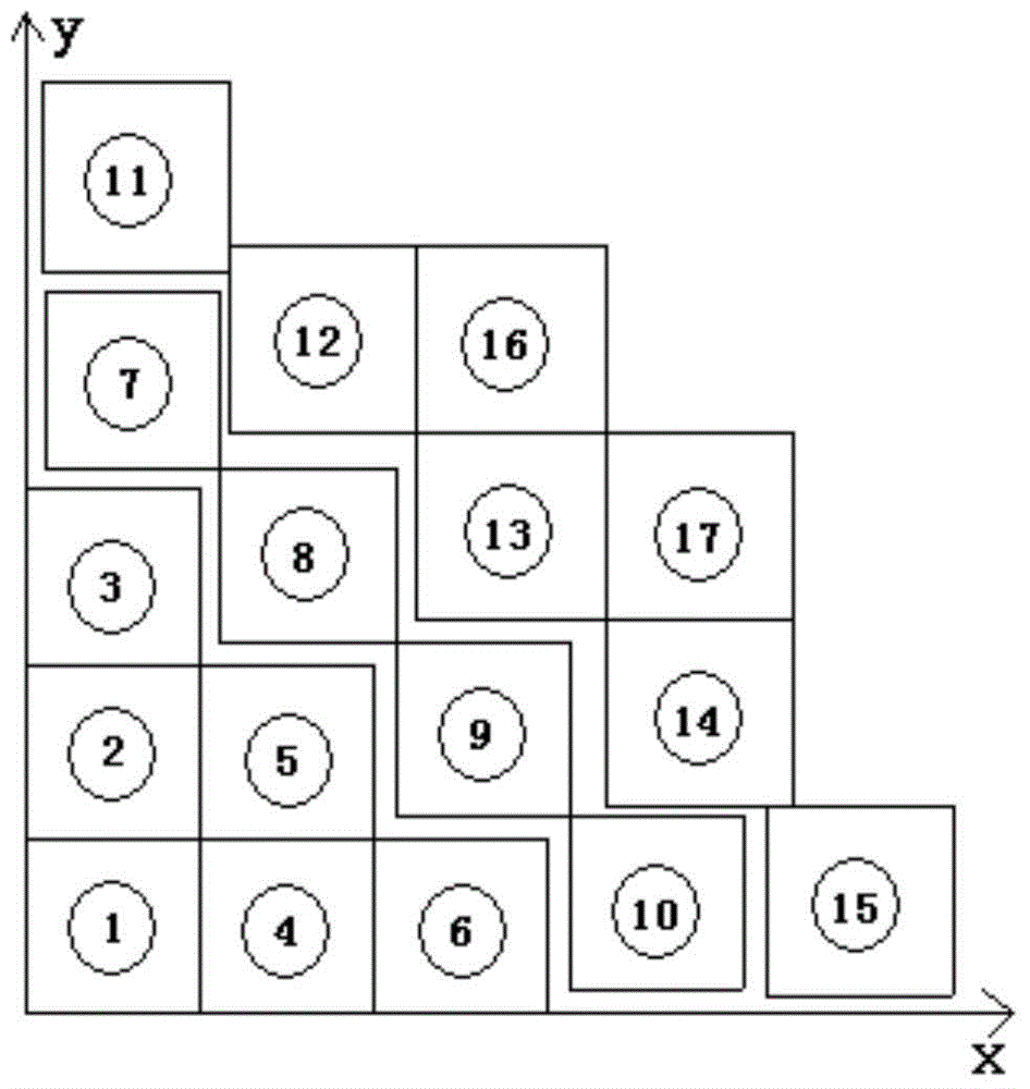
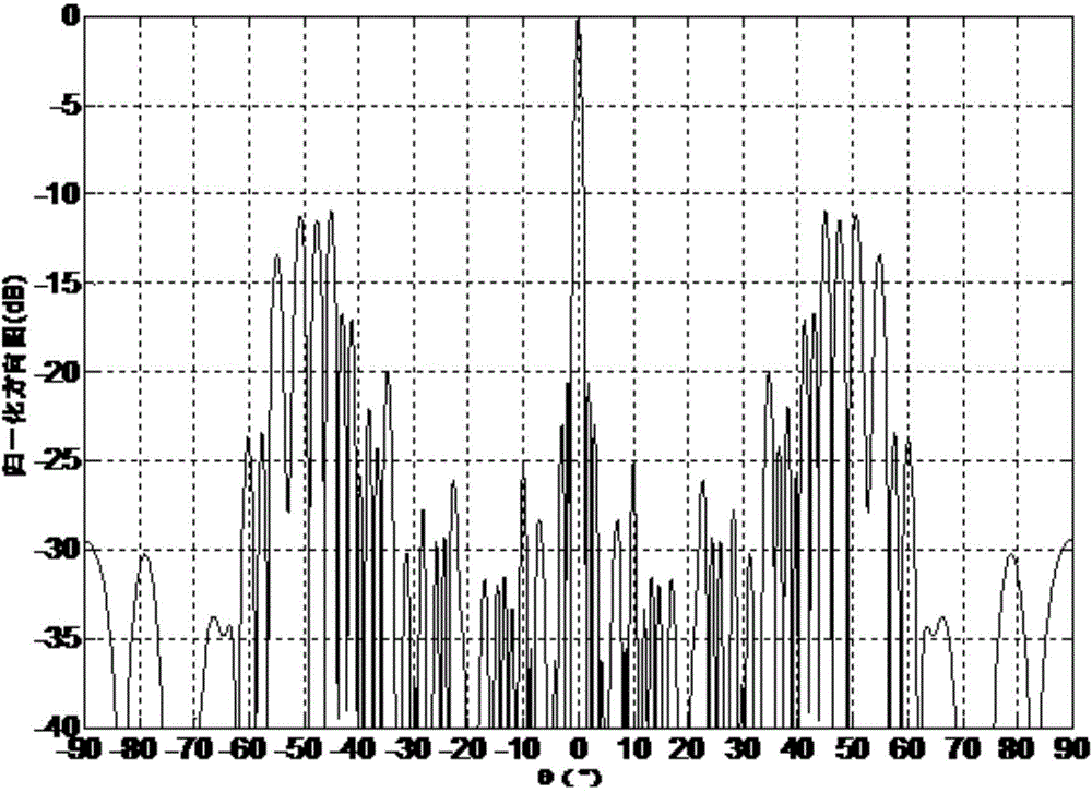
[0025] refer to figure 1 . In the following embodiments, the array layout for suppressing the grating lobes of the phased array antenna array with a large spacing is 1088 in total, the number of sub-arrays is 64, and the array layout of the grating lobes is less than -11dB is the best embodiment. 1 in the figure is the position of the unit, 16 units form a sub-array, the square frame is the edge of the sub-array, 2 in the figure is the center position of the sub-array with a square frame, there are 17 sub-arrays in the first quadrant, and the whole array has a total of 68 (4*17) sub-arrays, 1088 (4*17*16) units.

[0026] The arrangement of the whole array mainly includes two parts: one part is the arrangement of the units in the sub-array, and the other part is the arrangement between the sub-arrays. The whole phased array antenna array is divided into four parts ac...


PUM


Abstract

The invention provides a distribution method capable of restraining grating lobes of a large-space phased-array antenna. The distribution method is characterized in that the whole surface of an array antenna array is divided into four quadrants according to a rectangular coordinate system, and the four quadrants are rotationally symmetrical or axially symmetrical about the center of the quadrants; each quadrant comprises N subarrays, the edges of the N subarrays are not overlapped, and the N subarrays are distributed outwards in the direction of the radius of the array center in a sparsification mode to form an aperiodic array; each subarray comprises M units, the M units are distributed uniformly or disuniformly according to different grid modes, and space among N*M units is larger than a wave length; the shape of the edge of the array is an approximate round, oval, octangle or rectangle. By combining the array sparsification principle and the subarray-level aperiodic structure principle, the array with the space of a unit larger than the wave length is constructed, technical indexes including gain, resolution ratio and grating lobe restraint can be achieved with few antenna units, requirements are met, and cost of an antenna system is reduced.

Description

technical field [0001] The invention relates to a phased array antenna array method in the fields of navigation, communication, etc., in particular to a grating lobe suppression method for a large-space phased array antenna with an array element spacing of more than one wavelength. Background technique [0002] Phased array antennas are usually composed of a group of discrete radiating antennas, which can be arranged in a linear structure, or in a two-dimensional planar structure or a space arch structure. The amplitude and phase excitation of each radiating antenna can be independently controlled to form beams of any desired shape in space. [0003] There are various structural forms of array antennas. The most basic form is a linear array, which refers to an array antenna in which the centers of multiple radiating elements are on a straight line. The element spacing can be equal or unequal. When the centers of the antenna's radiating elements are arranged on a plane, it i...

Claims


Application Information

Patent Timeline
IPC IPC(8): H01Q21/28H01Q3/00
Inventor 王欣赵玉国陈超汪波刘华林黄先知曾传宝
Owner LINGBAYI ELECTRONICS GRP
Why Eureka
Try Eureka