
X-frequency-band noise coefficient automatic test system and method with LAN interface

An automatic test system, LAN interface technology, applied in the transmission system, transmission monitoring, electrical components, etc., can solve the problems of poor measurement accuracy, high measurement cost, slow test speed, etc., and achieve the effect of strong versatility and wide application fields

Inactive Publication Date: 2014-08-13
SHANGHAI SPACEFLIGHT ELECTRONICS & COMM EQUIP RES INST
View PDF9 Cites 4 Cited by
  • Summary
  • Abstract
  • Description
  • Claims
  • Application Information

AI Technical Summary

Problems solved by technology

For occasions with a small number of occasions, manual measurement can generally be used, and the measurement results are read and recorded manually. However, for applications with a large amount of data, the traditional manual measurement method will seriously affect the efficiency and data accuracy, and is not convenient. late data call
[0004] The receiving module under test working in the X-band needs to measure dozens of frequency points in total. Each frequency point needs to record information such as noise figure, gain, and test time. The amount of measurement data is large. Manually measure and record the above data of a receiving module takes longer
[0005] For example, TR (Transmitter and Receiver) components in active phased array radar range from a few hundred to tens of thousands. If the traditional manual testing method is used, the testing speed is slow, the efficiency is low, the measurement accuracy is poor, the instrument is easily damaged, and the measurement cost High, so it is necessary to establish an automatic test system to achieve accurate, fast and convenient testing of the noise figure of a large number of receiving modules. Processing speed and accuracy, reducing design costs, etc. are of practical significance

Method used


Image

  • X-frequency-band noise coefficient automatic test system and method with LAN interface
  • X-frequency-band noise coefficient automatic test system and method with LAN interface

Examples


Embodiment Construction

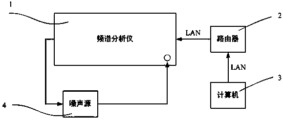
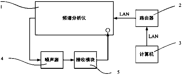
[0028] The technical solutions in the embodiments of the present invention will be clearly and completely described and discussed below in conjunction with the accompanying drawings of the present invention. Obviously, what is described here is only a part of the examples of the present invention, not all examples. Based on the present invention All other embodiments obtained by persons of ordinary skill in the art without creative efforts fall within the protection scope of the present invention.

[0029] In order to facilitate the understanding of the embodiments of the present invention, specific embodiments will be taken as examples for further explanation below in conjunction with the accompanying drawings, and each embodiment does not constitute a limitation to the embodiments of the present invention.

[0030] like figure 1 and figure 2 As shown, an X-band noise figure automatic test system using a LAN interface is used to automatically test the noise figure of the re...


PUM


Abstract

The invention discloses an X-frequency-band noise coefficient automatic test system with a LAN interface. The system is used for automatically testing the noise coefficient of a receiving module and comprises a spectrum analyzer, a noise source, a computer, a router and a network cable. The spectrum analyzer is connected with the output end of the receiving module, the noise source is connected with the input end of the receiving module, the LAN interface of the computer and the LAN interface of the spectrum analyzer are connected to the same LAN through the network cable and the router, and the noise source provides drive signals for the receiving module. The invention further provides an X-frequency-band noise coefficient automatic test method with the LAN interface. According to the X-frequency-band noise coefficient automatic test system and method with the LAN interface, the noise coefficient of the receiving module can be automatically tested rapidly, accurately and conveniently, noise coefficients of any multi-port network can be automatically tested, universality is high, and the application range is wide.

Description

technical field [0001] The invention relates to the field of noise figure automatic test, in particular to an automatic test system and method for measuring noise figure with large amount of data. [0002] Background technique [0003] Noise figure is an important parameter of amplifiers and receivers. The level of noise figure directly affects the sensitivity of the receiving system. It is generally required to be tested in all communication systems to facilitate system performance analysis. For occasions with a small number of occasions, manual measurement can generally be used, and the measurement results are read and recorded manually. However, for applications with a large amount of data, the traditional manual measurement method will seriously affect the efficiency and data accuracy, and is not convenient. Later data calls. [0004] The receiving module under test working in the X-band needs to measure dozens of frequency points in total. Each frequency point needs t...

Claims


Application Information

Patent Timeline
IPC IPC(8): H04B17/00
Inventor 王文伟姚崇斌
Owner SHANGHAI SPACEFLIGHT ELECTRONICS & COMM EQUIP RES INST
Learn More