
Sliding-vane-type oil delivery pump with springs

An oil pump and sliding vane technology, which is applied in the field of parts and components, can solve the problems of extremely high processing precision of parts, the inability to use high-pressure common rail systems, and poor low-speed adaptability, so as to achieve low processing precision requirements and avoid internal leakage. , to meet the effect of pump oil volume

Inactive Publication Date: 2014-08-20
辽阳钜锋汽车零部件有限公司
View PDF3 Cites 1 Cited by
  • Summary
  • Abstract
  • Description
  • Claims
  • Application Information

AI Technical Summary

Problems solved by technology

[0003] At present, the general oil delivery pump is a gear oil delivery pump, such as the HPO pump of Japan's Denso Corporation and the CP3 pump of the German Ph. There is always this gap between the shells, which causes internal leakage of diesel oil and reduces the efficiency of oil delivery; the processing accuracy of parts is extremely high, which is difficult to achieve with ordinary processing equipment
In recent years, although sliding vane oil transfer pumps have been introduced on the market, they are all large-scale and integrally structured, which cannot be used in high-pressure common rail systems, and have poor low-speed adaptability

Method used


Image

  • Sliding-vane-type oil delivery pump with springs

Examples


Embodiment approach 1

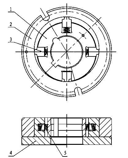
[0016] Such as figure 1 As shown, the rotor 1 is installed on the drive shaft of the high-pressure oil pump. There are 4 sliding slots equidistant around the rotor 1. The sliding piece 3 is installed in the sliding slot and can slide freely along the sliding slot. The sliding piece 3 is tightly attached to the eccentric ring. 2, the vane spring 5 is installed between the bottom of the chute and the vane 3, the eccentric ring 2 is set on the outer edge of the assembled rotor 1, vane 3 and vane spring 5, and the eccentric ring 2 is for The eccentricity of the axis of the drive shaft is 1mm.

Embodiment approach 2

[0018] Use 6 slides. Set 6 sliding slots equidistantly around the rotor 1, and 6 sliding vanes 3 and sliding vane springs 5 ​​are installed in the sliding slots; the eccentricity of the eccentric ring 2 is 2mm; the installation and technical conditions of other parts are the same as those of the implementation plan 1 .

Embodiment approach 3

[0020] Use 8 slides. Set up 8 slide slots equidistantly around the rotor 1, and install 8 slide plates 3 and slide plate springs 5 ​​in the slide slots; the eccentricity of the eccentric ring 2 is 3 mm; the installation and technical conditions of other components are the same as those of Embodiment 1 .

[0021] The operating mechanism of the present invention is: when the rotor 1 is driven to rotate by the drive shaft of the high-pressure oil pump, the sliding plate 3 is thrown out by the centrifugal force, and tightly fits on the inner cavity wall of the eccentric ring 2 . However, due to the eccentric installation of the rotor 1 in the inner cavity of the eccentric ring 2, the sliding vane 3 slides along the groove on the rotor 1, and the volume of the cavity between the two sliding vanes 3 changes from large to small, sucking in the low-pressure inlet. The diesel oil is compressed to the high-pressure outlet, so that the diesel pressure increases rapidly to meet the oil i...


PUM

PropertyMeasurementUnit
Eccentricityaaaaaaaaaa

Abstract

The invention discloses a sliding-vane-type oil delivery pump with springs. The sliding-vane-type oil delivery pump comprises a rotor, an eccentric ring, sliding vanes, an oil delivery pump cover and the sliding valve springs. The rotor is installed on a driving shaft of a high-pressure oil pump, sliding grooves are formed in the outer circle of the rotor in an equidistant mode, one sliding vane which can move in the sliding groove is placed in each sliding groove, the sliding vane springs are installed between the bottoms of the sliding grooves and the sliding vanes, the sliding vanes sliding along the sliding grooves are tightly attached to the inner cavity wall of the eccentric ring, the eccentric ring is arranged on the outer edge of a whole body in a sleeved mode, and the eccentric ring is attached to the oil delivery pump cover, wherein the whole body is formed by assembling the rotor, the sliding vanes and the sliding vane springs. In the sliding-vane-type oil delivery pump with the springs, the sliding vanes slide along the sliding grooves, under the effect of centrifugal force, the sliding vanes run in the mode of being tightly attached to the inner wall of the eccentric ring, and when the centrifugal force is insufficient, the centrifugal force can be compensated through the effect of the sliding vane springs. The sliding-vane-type oil delivery pump overcomes the defect that the inner portion of a diesel engine leaks, the low-speed adaptability of the oil delivery pump is enhanced, and due to the fact that the requirement for element machining precision is not high, the product cost is lowered.

Description

technical field [0001] The invention belongs to the field of diesel automobile manufacturing, in particular to a component used in a high-pressure oil pump of a diesel engine. Background technique [0002] The high-pressure common rail system is a new type of electronically controlled fuel injection system for diesel engines, including high-pressure oil pumps, common rail pipes, fuel injectors, and electronic control units. Since the high-pressure common rail system needs to supply sufficient quantity and sufficient high-pressure diesel oil during the high-speed rotation of the diesel engine, and to control the oil intake to flexibly change with the needs of the diesel engine, an oil delivery pump is required to provide a pressure of 0.5 MPa for the high-pressure common rail system. [0003] At present, the general oil delivery pump is a gear oil delivery pump, such as the HPO pump of Japan's Denso Corporation and the CP3 pump of the German Ph. There is always this gap betw...

Claims


Application Information

Patent Timeline
IPC IPC(8): F02M59/12F02M59/44
Inventor 臧广辉王雷奚阳韩宜龙李世明白阳柳继月戴宏伟范永新康凯
Owner 辽阳钜锋汽车零部件有限公司
Learn More