
An in-pipe redistribution film generating device for automatically cleaning smoke and dirt outside the pipe

A generation device and automatic cleaning technology, which is applied in the direction of generator/analyzer, refrigeration components, refrigerators, etc., can solve problems such as uneven distribution of liquid film, difficult wetting of heat exchange surface, increase of solution saturation temperature, etc., to achieve enhanced Effect of heat and mass transfer coefficient, uniform distribution of liquid film, and improvement of mass transfer coefficient

Active Publication Date: 2016-02-24
山东东岳能源交口肥美铝业有限责任公司
View PDF8 Cites 0 Cited by
  • Summary
  • Abstract
  • Description
  • Claims
  • Application Information

AI Technical Summary

Problems solved by technology

[0003] On the other hand, most of the existing absorption refrigeration generators are immersion type and spray type, and the immersion type generator is greatly affected by the static pressure of the liquid, which will increase the saturation temperature of the solution inside the liquid, making the driving force weakened, reducing the deflation range
The spray generator can effectively overcome the influence of hydrostatic pressure, but it is difficult to completely wet the heat transfer surface, and the heat transfer effect will also be affected
The use of a falling film generator can effectively avoid the influence of the static pressure of the solution. However, due to the change in the physical properties of the falling film tube wall, the distribution of the liquid film is often uneven, and even the phenomenon of falling film dry tube, channel flow or stream flow will occur. Reduce the effective occurrence area of ​​the liquid film, resulting in a decrease in the occurrence rate

Method used


Image

  • An in-pipe redistribution film generating device for automatically cleaning smoke and dirt outside the pipe
  • An in-pipe redistribution film generating device for automatically cleaning smoke and dirt outside the pipe
  • An in-pipe redistribution film generating device for automatically cleaning smoke and dirt outside the pipe

Examples


Embodiment Construction

[0033] The technical solution of the present invention will be described in detail below in conjunction with the accompanying drawings.

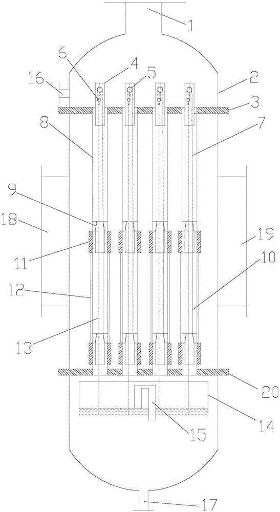
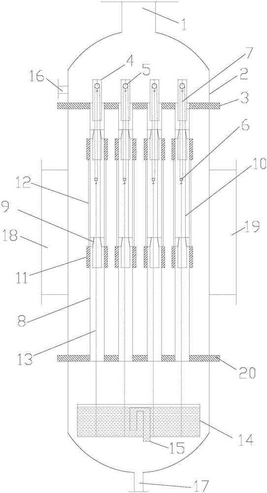
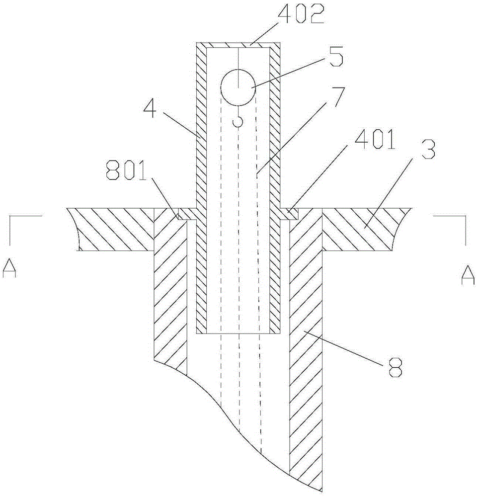
[0034] like figure 1 and figure 2As shown, a pipe re-distribution film generation device for automatic cleaning of smoke outside the pipe of the present invention includes a housing 2, an upper baffle 3 located in the housing 2, a lower baffle 20, n film distribution units and Suspension receiving basin 14. The top of the casing 2 is provided with a gas outlet 1, the bottom of the casing 2 is provided with a dilute solution outlet 17, and the side wall of the casing 2 is provided with a flue gas heat source inlet 18 and a flue gas heat source outlet 19 corresponding to each other. A concentrated solution inlet 16 is also provided on the side wall of the body 2 . The upper baffle 3 and the lower baffle 20 are respectively fixedly connected to the inner wall of the casing 2 , and the upper baffle 3 is located above the lower baffle 20 . T...


PUM


Abstract

The invention discloses an inter-pipe redistributed film generation device capable of automatically cleaning away smoke dirt outside a pipe. The inter-pipe redistributed film generation device comprises a shell, an upper baffle, a lower baffle, a film distribution unit and a hoisting liquid receiving pot. A siphon pipe is arranged in the hoisting liquid receiving pot. Each film distribution unit comprises an initial film distribution device, a fixed pulley, a movable pulley, a pulley line, a falling film pipe, a film redistribution device, an ash scraping ring and a bearing rope, wherein the top end of the falling film pipe is connected to the upper baffle, the bottom end of the falling film pipe is connected to the lower baffle, the initial film distribution device is located in a through hole in the upper baffle, the fixed pulley is fixedly connected to the initial film distribution device, the two ends of the pulley line are connected to a pulley hook of the fixed pulley and the top end of the film redistribution device, the ash scraping ring is located outside the falling film pipe, magnetic force exists between the ash scraping ring and the film redistribution device, and the two ends of the bearing rope are connected with the movable pulley and the hoisting liquid receiving pot. In the inter-pipe distributed film generation device, the film redistribution devices can reciprocate in the pipe for film redistribution, occurrence of channeling or plume is effectively restrained, liquid film distribution is uniformized, and dust accumulated outside the pipe is removed through the ash scraping devices outside the pipe.

Description

technical field [0001] The invention belongs to a generation-enhancing heat and mass transfer device in the technical field of absorption refrigeration utilizing waste heat of flue gas, and specifically relates to an in-pipe redistribution film generation device that automatically cleans smoke and dirt outside a pipe. Background technique [0002] my country's industrial flue gas reserves are rich in waste heat, and the effective use of waste heat is of great significance to my country's energy-saving and emission-reduction strategies. At present, the utilization of industrial waste heat and waste heat is mainly to generate hot water or steam, which increases intermediate heat exchange equipment such as boilers, resulting in increased investment and increased heat exchange losses. The flue gas discharge temperature is generally above 200°C. Using the waste heat of the flue gas directly as a heat source to drive the generator equipment of absorption refrigeration can effectiv...

Claims


Application Information

Patent Timeline
Patent Type & Authority Patents(China)
IPC IPC(8): F25B33/00
Inventor 杨柳杜垲
Owner 山东东岳能源交口肥美铝业有限责任公司
Learn More