Multistage gas-liquid parallel flow devolatilization technology as well as devolatilization device

A technology of devolatilization device and liquid seal device, which is applied in liquid degassing, organic chemistry, steam distillation, etc., can solve the problems of high manufacturing and operating costs, small gas-liquid flux, and high manufacturing costs, and achieve manufacturing and operating costs Low pressure, large gas-liquid passing capacity, and wide application range

Inactive Publication Date: 2014-09-10
TIANJIN YOUHUA SCI & TECH
View PDF5 Cites 6 Cited by
  • Summary
  • Abstract
  • Description
  • Claims
  • Application Information

AI Technical Summary

Problems solved by technology

[0005] Proposed a method for removing volatile components in the molten formaldehyde polymer in Chinese patent CN86107755, the method has adopted a three-stage disc type devolatilizer to remove formaldehyde and other volatile substances from the molten formaldehyde polymer ( Such as triethylamine and water), but its equipment structure is too complicated, and its manufacturing and operating costs are relatively high
[0006] Chinese patent CN1541742A proposes a slit falling film devolatilization tower, which relies on gravity and gas-liquid phase surface renewal for devolatilization, but due to the lack of a stripping stage, the devolatilization efficiency is low, and the internal structure is complicated. higher cost
However, due to the countercurrent flow of the gas-liquid two-phase flow, the gas-liquid flux is small and the pressure drop is large.

Method used


Image

  • Multistage gas-liquid parallel flow devolatilization technology as well as devolatilization device
  • Multistage gas-liquid parallel flow devolatilization technology as well as devolatilization device

Examples


Embodiment 1

[0021] Embodiment 1: removal of CO2 by aqueous solution of ethylene oxide.

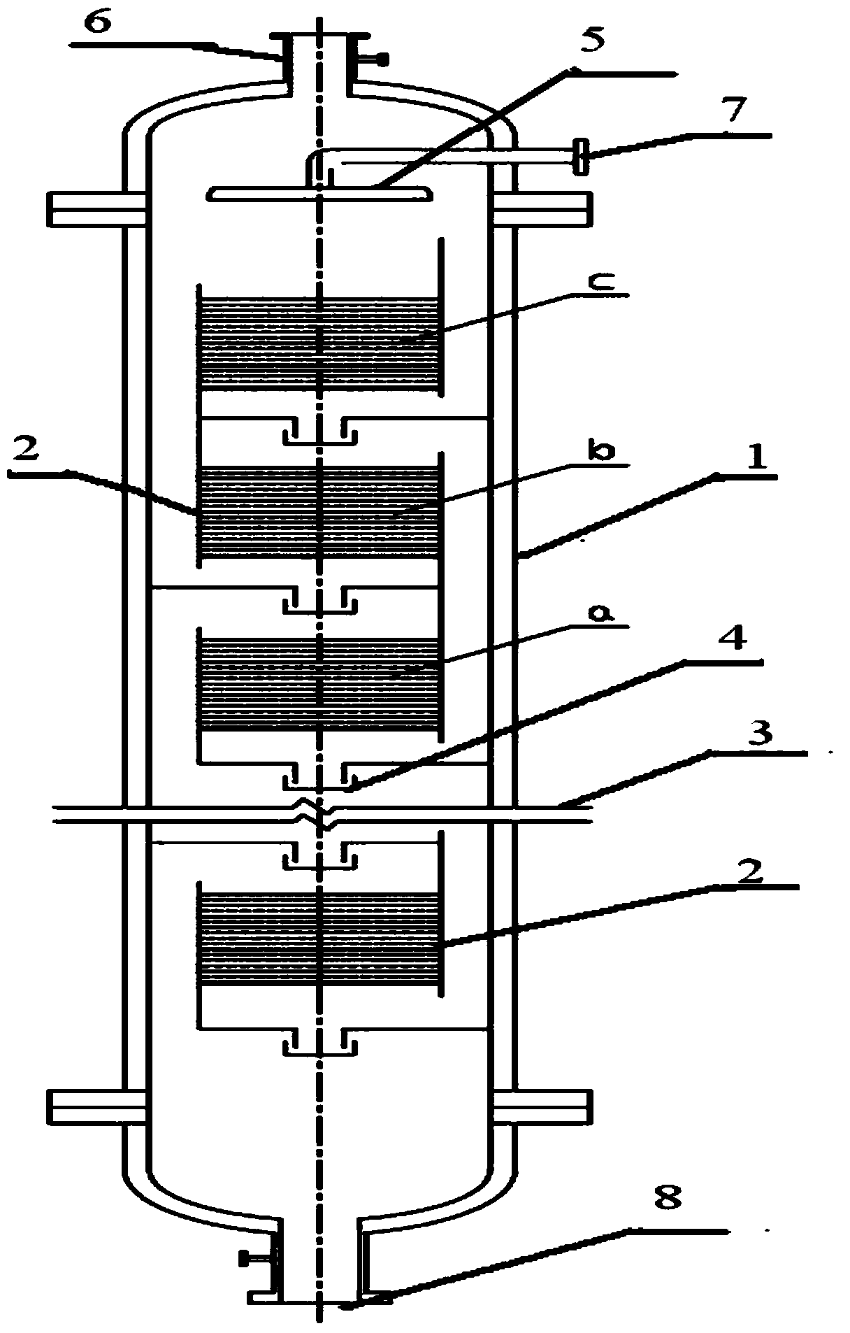
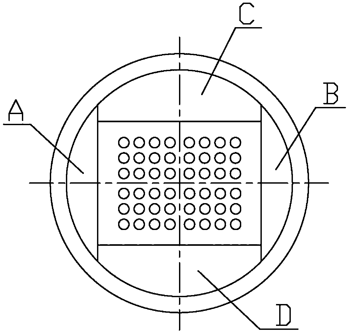
[0022] In this example, the diameter of the devolatilization tower is 1100mm, the height is 7600mm, and the packing tray is 600mm×150mm. There are 3 sections of packing, each section has 26 trays, and the distance between adjacent trays is 25mm.

[0023] The ethylene oxide aqueous solution containing 2% CO2 enters the tower, the temperature is 50°C, the flow rate is 25000-30000kg / h, the gas volume (water vapor) is 1000-1900kg / h, and the pressure inside the tower is 0.16MPa (absolute pressure). The carbon dioxide in the aqueous solution of ethylene oxide can be removed from the tower.

Embodiment 2

[0024] Embodiment 2: Removal of styrene in polystyrene polymer solution.

[0025] In this example, the diameter of the devolatilization tower is 1200mm, the height is 8000mm, and the packing tray is 620mm×170mm. There are 3 sections of packing, each section has 28 trays, and the distance between adjacent trays is 25mm.

[0026] The polystyrene solution containing 25% styrene enters the tower, the temperature is 200°C, the flow rate is 28000-34000kg / h, the gas volume (water vapor) is 1500-2400kg / h, and the pressure inside the tower is 0.15MPa (absolute pressure). The residual monomer content in the outgoing polystyrene product is below 200ppm.


PUM

PropertyMeasurementUnit
viscosityaaaaaaaaaa

Abstract

The invention relates to a multistage gas-liquid parallel flow devolatilization technology. The multistage gas-liquid parallel flow devolatilization technology is characterized in that a devolatilization tower mainly structurally comprises a tower body, a group or multiple groups of padding sections, a baffle, liquid seal devices, and a liquid distributor; materials enter the tower via the liquid distributor from the top of the tower; stripping stream is introduced or not from the bottom of the tower as required; in the padding sections, a gas and a liquid flow in parallel, and flow through a sieve tray to form a devolatilization interface so as to perform gas-liquid mass transfer. The multistage gas-liquid parallel flow devolatilization technology has the advantages of full gas-liquid contact, high gas-liquid passing capacity, no flooding restriction on two-phase load, small resistance and the like, has extremely high gas-liquid mass transfer efficiency, can be used for removing soluble gases in waste water and volatile substances in a polymer solution, and has extremely high popularization value.

Description

technical field [0001] The invention relates to a multistage gas-liquid co-current devolatilization process and a devolatilization device, in particular to a devolatilization method and a device for efficiently removing volatile substances from a polymer solution. Background technique [0002] The devolatilization process is an important link in polymer production, and its main function is to separate low molecular weight volatile components from the liquid phase to obtain qualified liquid phase products. [0003] Generally, measures to strengthen the devolatilization process mainly include 1. Strengthening operating conditions, such as increasing the temperature of the devolatilization system, etc.; 2. Adding low-boiling point devolatilization aids to reduce the partial pressure of volatile components in the gas phase; 3. Multi-stage devolatilization ; 4. Increase the gas-liquid two-phase interface and strengthen surface renewal. [0004] There are many forms of devolatili...

Claims


Application Information

Patent Timeline
Patent Type & Authority Applications(China)
IPC IPC(8): B01D19/00B01D3/38C07D303/04C07D301/32C08F12/08C08F6/10
Inventor 费昱恺张志烨
Owner TIANJIN YOUHUA SCI & TECH
Why Eureka
Try Eureka