Shell and tube type sewage heat exchanger convenient to clean

A shell-and-tube heat exchanger technology, applied in the direction of the heat exchanger shell, indirect heat exchanger, heat exchanger type, etc., can solve the problem of large pressure-bearing area, reduced heat exchange area, and easy leakage of the cleaning door and other problems, to achieve the effect of easy cleaning, improving heat transfer efficiency and reducing dead zone

Inactive Publication Date: 2014-08-20
王方
View PDF7 Cites 4 Cited by
  • Summary
  • Abstract
  • Description
  • Claims
  • Application Information

AI Technical Summary

Problems solved by technology

However, this technical solution can only use the mechanical method of opening the cleaning door for cleaning, and it is difficult to achieve thorough cleaning; the pressure-bearing area of ​​the cleaning door is large, and it is prone to leakage; and it adopts a wide and narrow flow channel, so the unit volume The heat exchange area inside is reduced; in addition, the heat exchanger uses more metal materials, and the cost is higher

Method used


Image

  • Shell and tube type sewage heat exchanger convenient to clean
  • Shell and tube type sewage heat exchanger convenient to clean
  • Shell and tube type sewage heat exchanger convenient to clean

Examples


Embodiment 1

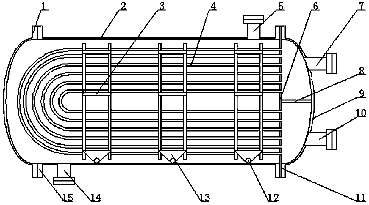
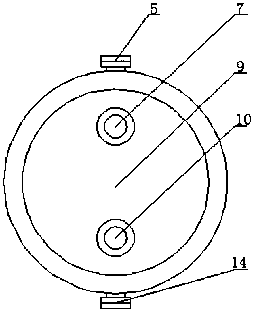
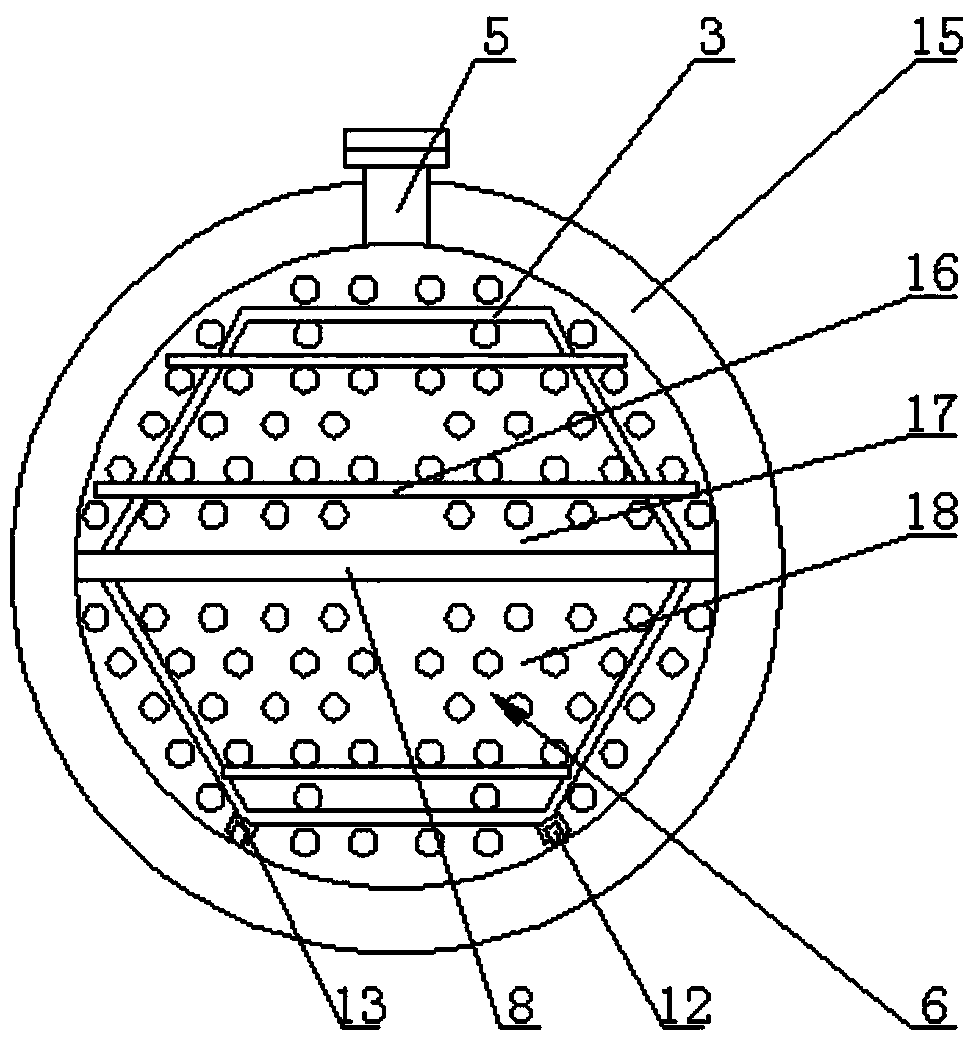
[0051] A heat exchange system, which has a structure including multiple shell and tube sewage heat exchangers 21, a water source heat pump unit 24, and a heating device 22. The water source heat pump unit is connected to a plurality of heat supply units connected in parallel through a hot water circulating pump 23 Equipment, the water outlet end of the other end of the water source heat pump unit is connected in parallel to the clear water inlets 10 of all shell and tube sewage heat exchangers through the clean water circulation pump 25, and the water inlet end of the other end of the water source heat pump unit is connected in parallel to all shells The clean water outlet 7 of the tubular sewage heat exchanger, the sewage inlet 5 of all shell and tube sewage heat exchangers are connected in parallel and connected to the sewage source 27 through the sewage pump 26, and the sewage outlet 14 of multiple shell and tube sewage heat exchangers Connect the sewage source after being co...

Embodiment 2

[0054] A heat exchange system, which has a structure including multiple shell and tube sewage heat exchangers 21, a water source heat pump unit 24, and a heating device 22. The water source heat pump unit is connected to a plurality of heat supply units connected in parallel through a hot water circulating pump 23 Equipment, the outlet end of the other end of the water source heat pump unit is connected to the clear water inlet 10 of the first shell and tube sewage heat exchanger through the clean water circulation pump 25, and the inlet end of the other end of the water source heat pump unit is connected to the last shell tube The clean water outlet 7 of the type sewage heat exchanger is connected to the clean water outlet of each shell and tube sewage heat exchanger from the first shell and tube sewage heat exchanger to the last shell and tube sewage heat exchanger. The clean water inlet of a shell and tube sewage heat exchanger, from the last shell and tube sewage heat exchan...


PUM


Abstract

The invention relates to a shell and tube type sewage heat exchanger, in particular to a shell and tube type sewage heat exchanger convenient to clean. The shell and tube type sewage heat exchanger comprises a shell and a heat exchange pipe bundle. A sewage inlet and a sewage outlet are manufactured in the shell. A detachable clean water end socket is installed at the end of one side of the shell. The heat exchange pipe bundle capable of being taken out is installed in the portion, on the inner side of the clean water end socket, of the shell in an embedded mode. A pipe bundle end plate is installed between the clean water end socket and the end of the shell in an embedded mode. An end socket partition plate is installed between the pipe bundle plate and the clean water end socket. A water outlet cavity of one side of the end socket partition plate is respectively communicated with a clean water outlet and one end, embedded in the pipe bundle end plate, of the heat exchange pipe bundle, and a water inlet cavity of the other side of the end socket partition plate is communicated with a clean water inlet and the other end, embedded in the pipe bundle end plate, of the heat exchange pipe bundle. A detachable end socket is installed at the end of the other side of the shell. According to the shell and tube type sewage heat exchanger, the clean water end socket and the sewage end socket can be disassembled according to the actual situations, and the shell and the heat exchange pipe bundle can be cleaned.

Description

Technical field [0001] The invention relates to a shell and tube type sewage heat exchanger, in particular to a shell and tube type sewage heat exchanger that is easy to clean. Background technique [0002] With the increasingly severe environmental pollution situation, water-source heat pump technology that uses urban sewage, reclaimed water and other surface water as heat sources has attracted more and more attention from manufacturers because of its ability to reduce industrial and heating and air conditioning energy consumption, energy saving and emission reduction. Especially in the fields of petroleum and chemical industry, the technology of extracting heat energy from industrial waste water and realizing waste heat recovery and utilization of sewage has become an important way to save energy in industry and construction. [0003] Among the heat exchangers in the above-mentioned fields, shell and tube heat exchangers are the most widely used. The structure of the shell and tu...

Claims


Application Information

Patent Timeline
Patent Type & Authority Applications(China)
IPC IPC(8): F28D7/00F28F9/06F28F9/013F28F9/00F25B30/06
Inventor 王方
Owner 王方
Why Eureka
Try Eureka