Heating equipment for electrical heating card thermoluminescence dose measurement

A thermoluminescence dose and heating device technology, which is applied in measurement devices, optical radiation measurement, photometry, etc., can solve the problems of inability to linearize multiple detectors, program heating, etc., and achieve the effect of close contact and increased contact degree.

Inactive Publication Date: 2014-08-20
北京瑞辐特辐射测量仪器有限公司
View PDF4 Cites 2 Cited by
  • Summary
  • Abstract
  • Description
  • Claims
  • Application Information

AI Technical Summary

Problems solved by technology

[0004] The embodiment of the present invention proposes a heating device for thermoluminescence dose measurement of an electric heating card, which solves the problem in the prior art that linear and programmed heating of multiple detectors cannot be performed at one time

Method used


Image

  • Heating equipment for electrical heating card thermoluminescence dose measurement
  • Heating equipment for electrical heating card thermoluminescence dose measurement
  • Heating equipment for electrical heating card thermoluminescence dose measurement

Examples


Embodiment 1

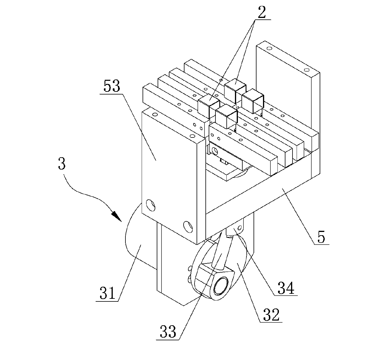
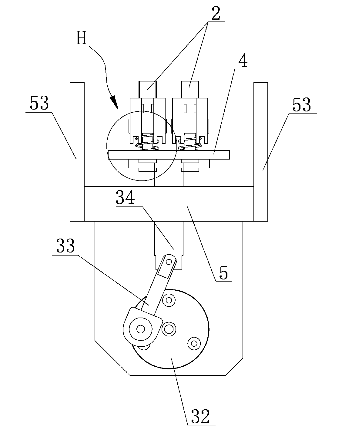
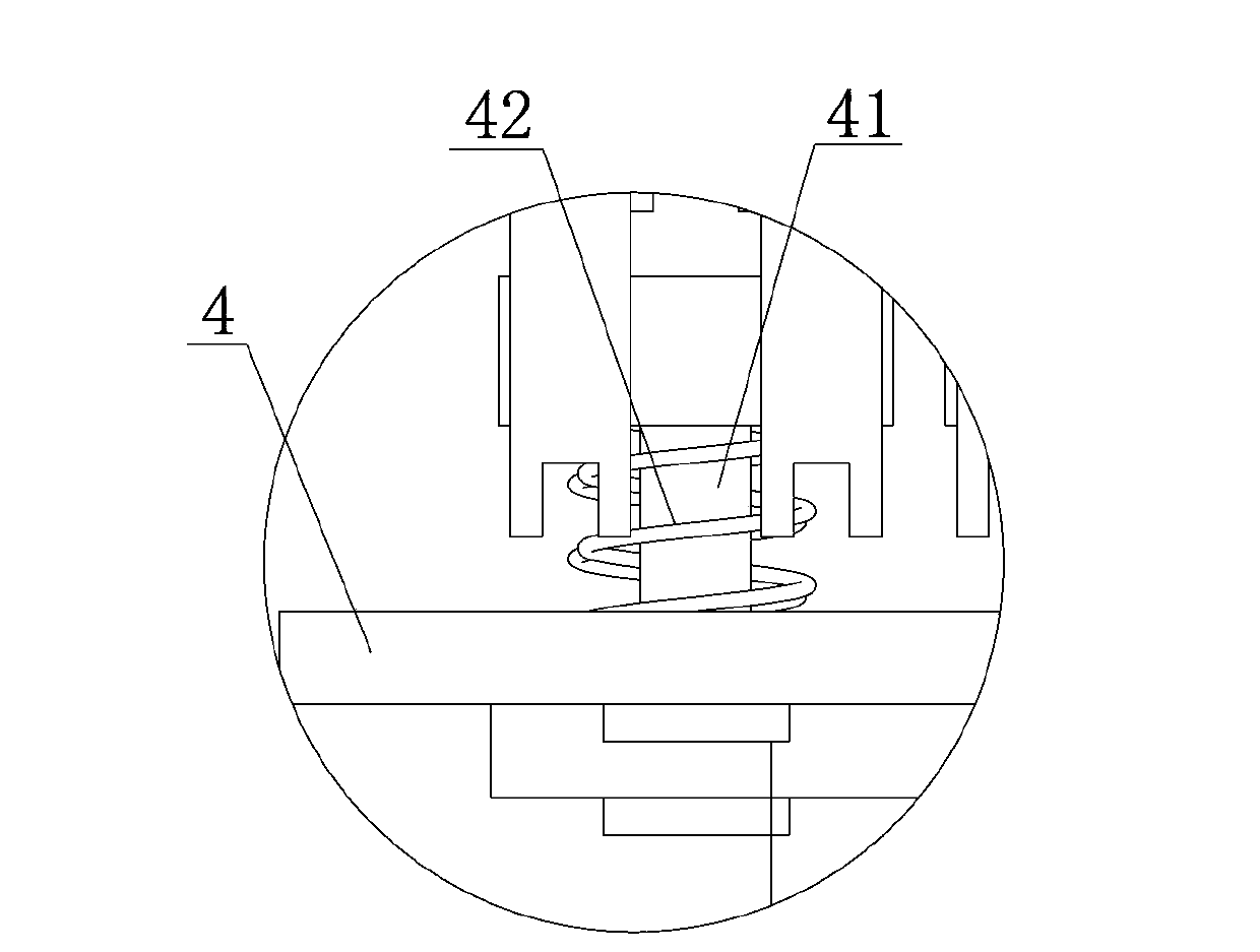
[0026] Such as figure 1 , figure 2 with Figure 4 Commonly shown is an embodiment of the heating device for thermoluminescent dose measurement of the electric heating card of the present invention, including an electric heating mechanism and a power mechanism. Such as Figure 5 with Image 6 Commonly shown is a schematic structural view of the workbench of this embodiment.

[0027] The workbench in this embodiment is a detector tray 1, and a plurality of (four shown in the figure) detector grooves 11 for accommodating detectors are opened on the detector tray 1, as Figure 7 shown, for Figure 5 In the partially enlarged schematic diagram of the position I, the detector tray 1 is also provided with a metal sheet 12 located on the back of the detector groove 11 (ie, the detector). The detector tray 1 is set horizontally when in use, the detector groove 11 is on the top, and the metal sheet 12 is on the bottom. At the same time, a limiter is provided above the detector tr...

Embodiment 2

[0039] The power source of the heating device for measuring the thermoluminescent dose of the electric heating card can also be a vertical cylinder, and the heating head 2 can be directly fixed on the top of the piston of the cylinder, or can be fixed on the top of the cylinder by driving rod 34 and copper plate 4. The piston top of the cylinder.

[0040] The difference between this embodiment and the first embodiment is only that the driving mode is different, and the crank-link mechanism in the first embodiment is replaced by a cylinder, which can also realize the heating function. The rest of the structure in this embodiment is the same as that in Embodiment 1, and will not be repeated here.

[0041] In short, the heating device uses a single-column four-head electric heating device to heat four detectors at one time, which can realize automatic sample replacement and automatic measurement. Moreover, the thermal contact between the heating head and the workbench is good, an...


PUM


Abstract

The invention provides heating equipment for electrical heating card thermoluminescence dose measurement, and is used for solving the problem in existing electrical heating technology that linear and programmed heating and automatic measurement cannot be performed on multiple thermoluminescence detectors in one time. The heating equipment for electrical heating card thermoluminescence dose measurement includes a workbench, an electrical heating mechanism and a power mechanism, the workbench is used for placing detected dosimeter cards, a limiting body is arranged at an upper side of the workbench, the electrical heating mechanism includes a plurality of heating heads, the plurality of heating heads are located under the workbench and used for heating the detected detectors on the workbench, the power mechanism includes a power source and a lifting buffer mechanism driven by the power source, and the electrical heating mechanism is arranged on the lifting buffer mechanism and used for adjusting the positions of the heating heads. The measuring equipment is simple in structure and convenient to operate, and can realize linear and programmed heating of multiple detectors in one time, thereby accurately measuring the exposure dose of the detectors.

Description

technical field [0001] The invention relates to the technical field of an electric heating mechanism for thermoluminescent dose measurement, in particular to a heating device for thermoluminescent dose measurement of an electric heating card that can realize linear and programmed heating of multiple detectors at one time. Background technique [0002] Under natural conditions, after the detector is irradiated by radiation, it will store the absorbed energy. When it is heated, the detector will release the absorbed energy in the form of light. The intensity of the light signal released by the detector and the irradiation The dose is linear, so the dose to the detector can be determined by measuring the light intensity emitted by the detector. This phenomenon is one-time, that is, after the detector is subjected to radiation, light will be released only when it is heated for the first time. In the subsequent heating process, unless it receives radiation again, it will not emit...

Claims


Application Information

Patent Timeline
Patent Type & Authority Applications(China)
IPC IPC(8): G01J1/02
Inventor 张建陈伟程旭刘书彦
Owner 北京瑞辐特辐射测量仪器有限公司
Why Eureka
Try Eureka