Swing wear life test clamp of joint bearing

A joint bearing and test fixture technology, applied in the field of testing, can solve the problems of high failure probability, low installation and disassembly efficiency, and high test cost, and achieves the effects of reliable performance, improved installation and disassembly efficiency, and saving test time.

Inactive Publication Date: 2014-08-20
CHINA AERO POLYTECH ESTAB
View PDF5 Cites 14 Cited by
  • Summary
  • Abstract
  • Description
  • Claims
  • Application Information

AI Technical Summary

Problems solved by technology

The structure of this test fixture is complicated, the probability of failure is high, the installation and disassembly efficiency is low, and the test cost is high

Method used


Image

  • Swing wear life test clamp of joint bearing
  • Swing wear life test clamp of joint bearing

Examples


Embodiment Construction

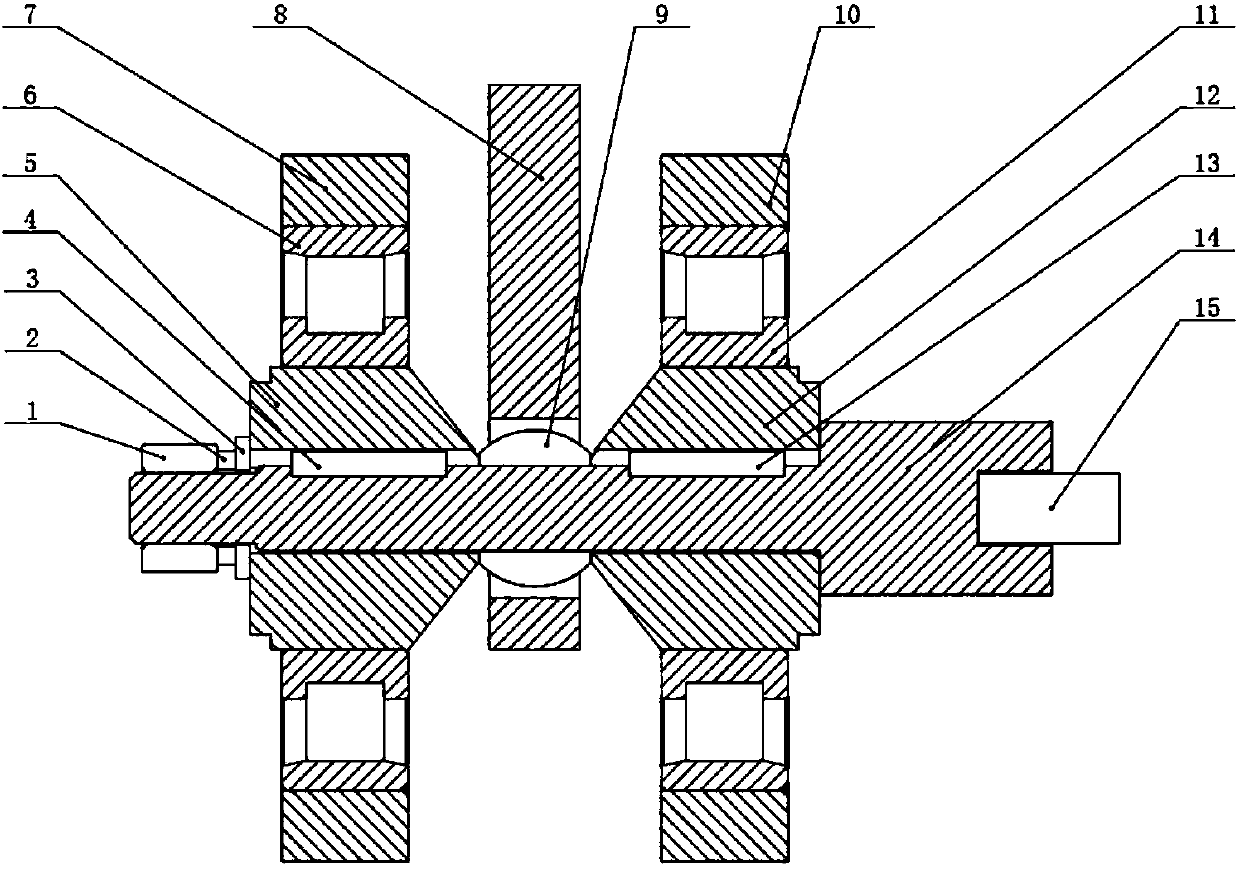
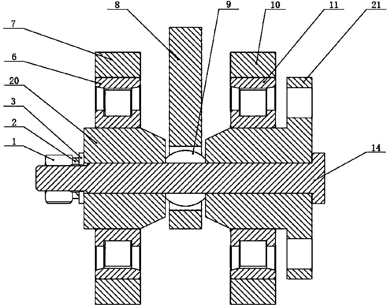
[0011] The present invention will be described in detail below in conjunction with the accompanying drawings. Such as figure 2 As shown, the joint bearing swing wear life test fixture includes a mandrel 14 without a keyway, a left top sleeve 20, a right top sleeve 21, a left support bearing 6, a right support bearing 11, a left support 7 and a right support 10 and the loading plate 8, the mandrel 14 passes through the right top sleeve 21, the joint bearing 9 installed in the loading plate 8 and the left top sleeve 20 in turn, and the right top sleeve 21 is connected with the drive system at one end with a flange, and the other end is on the joint An inner ring end face of the bearing 9; the mandrel 14 has a shaft shoulder, and the shaft shoulder is pushed against the flanged end face of the right top sleeve 21, the shaft head of the mandrel 14 has an external thread, and the nut 1 and the spring on the mandrel 14 shaft head The washer 2 and the flat washer 3 make the left to...


PUM


Abstract

The invention belongs to the technical field of tests, and relates to a swing wear life test clamp of a joint bearing. The strength and the rigidity of a central spindle of the swing wear life test clamp of the joint bearing are improved due to the fact that a spindle body and a spindle head of the central spindle are respectively provided with a key groove, and the load and torque borne by the central spindle are also reduced. A left ejection sleeve and a right ejection sleeve are used for clamping the inner circle of the joint bearing through nuts, spring washers, flat washers and a spindle shoulder of the central spindle. A drive system drives the joint bearing to achieve periodic swinging through the friction force between parts in the test clamp. Spindle body keys and spindle head keys are not used in the test clamp, so that the performance is reliable, the structure is simple, machining is convenient, the test clamp cost is lowered, mounting and dismounting are convenient, the strength of mounting and dismounting is reduced, the efficiency of mounting and dismounting is improved, impact of keys is avoided, the probability of occurrence of test faults is lowered, the stability of the test clamp is improved, the test time is saved, and the test cost is lowered.

Description

technical field [0001] The invention belongs to the technical field of testing, and relates to a jig for testing the swing wear life of a joint bearing. Background technique [0002] At present, the fixtures used in the swing wear life test of joint bearings are as follows: figure 1 as shown, [0003] This test fixture consists of a mandrel 14, a shaft head key 15, a left flat key 4, a right flat key 13, a left top block 5, a right top block 12, a left support bearing 6, a right support bearing 11, a left support 7 and Right bearing 10 etc. are formed. Mandrel 14 axle heads have keyway, are connected with driving system with key 15 by axle head. Mandrel 14 axle bodies have keyway, are connected with left top block 5 with left flat key 4, are connected with right top block 12 with right flat key 13. The mandrel 14 has a shaft shoulder, and the inner ring of the joint bearing 9 installed in the loading plate 8 is clamped by the left jacking block 5 and the right jacking bl...

Claims


Application Information

Patent Timeline
Patent Type & Authority Applications(China)
IPC IPC(8): G01M13/04G01N3/04
Inventor 李彦伟林晶张令赵颖春
Owner CHINA AERO POLYTECH ESTAB
Why Eureka
Try Eureka