

MIMO sparse array ultrasonic measurement methods and system for fluctuation interface
A technology of ultrasonic measurement and sparse array, which is applied in the direction of radio wave measurement system, measurement device, liquid/fluid solid measurement, etc., and can solve problems such as large measurement errors
- Summary
- Abstract
- Description
- Claims
- Application Information
AI Technical Summary
Problems solved by technology
Method used
Image

Examples
Embodiment 1
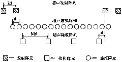
[0119] Such as figure 2 As shown, the criterion for the arrangement of the ultrasonic sparse array element array in this embodiment is: if the spacing of the virtual array elements is set to be d, then the array element spacing of each group of transmitting arrays is d T =2×d, the element spacing of the receiving array is d R =M×d, the distance between each transmitting array and the edge of the receiving array is d. The implementation examples of the present invention all adopt 4 transmitting array elements, whose coordinates are respectively (-135,0), (-105,0), (105,0), (135,0) (unit: mm), and 4 receiving elements Array element, its coordinates are (-90, 0), (-30, 0), (30, 0), (90, 0) (unit: mm).
[0120] The center frequency of the chirp signal is set to 300KHZ, the bandwidth is 60KHZ, and the code in Table 1 below is used for the balanced Gold code.
[0121]
[0122] Table 1 Optimized balanced Gold code with a code length of 127
[0123] The linear frequency modula...
Embodiment 2
[0128] The array of ultrasonic array elements is arranged as figure 2 As shown, the center point of the array is taken as the origin of the coordinate axis, the center frequency of the chirp signal is set to 300KHZ, the bandwidth is 60KHZ, the point target position is set at (14°, 1.2m), and the beamforming focus is checked by changing the position of the beamforming focus The influence of the deviation on the measurement accuracy, where the deviation of the beamforming focus is divided into two directions, the axial direction and the azimuth angle of the synthetic beam. The measurement error is stable within 0.6mm when the beamforming focal point is offset along the composite beam axis in the range of 20mm and the echo SNR is higher than 5, however, the azimuth angle offset will cause a considerable beamforming focal point offset, Cause serious measurement errors, the corresponding simulation (using time-sharing transmission mode) results are as follows Image 6 . from I...
Embodiment 3
[0130] The array of ultrasonic array elements is arranged as figure 2 , take the center point of the array as the origin of the coordinate axis, the center frequency of the chirp signal is set to 300KHZ, the bandwidth is 60KHZ, the balanced Gold code adopts the code in Table 1, and the time-sharing and simultaneous transmission modes are used respectively under different signal-to-noise ratios. Single-point target measurement, the range of signal-to-noise ratio is -30 ~ 15dB, and the point target position is set at (0°, 0.5m). The steps are the same as in Example 1, and the error diagrams of the two transmission modes under different signal-to-noise ratios are obtained ( Figure 7 ).
[0131] from Figure 7 It can be seen from (a) that the method of the present invention can accurately measure the target distance under the condition of low signal-to-noise ratio, especially in the simultaneous transmission mode, it can still work reliably under the condition that the signal-...
PUM
 Abstract
Description
Claims
Application Information