

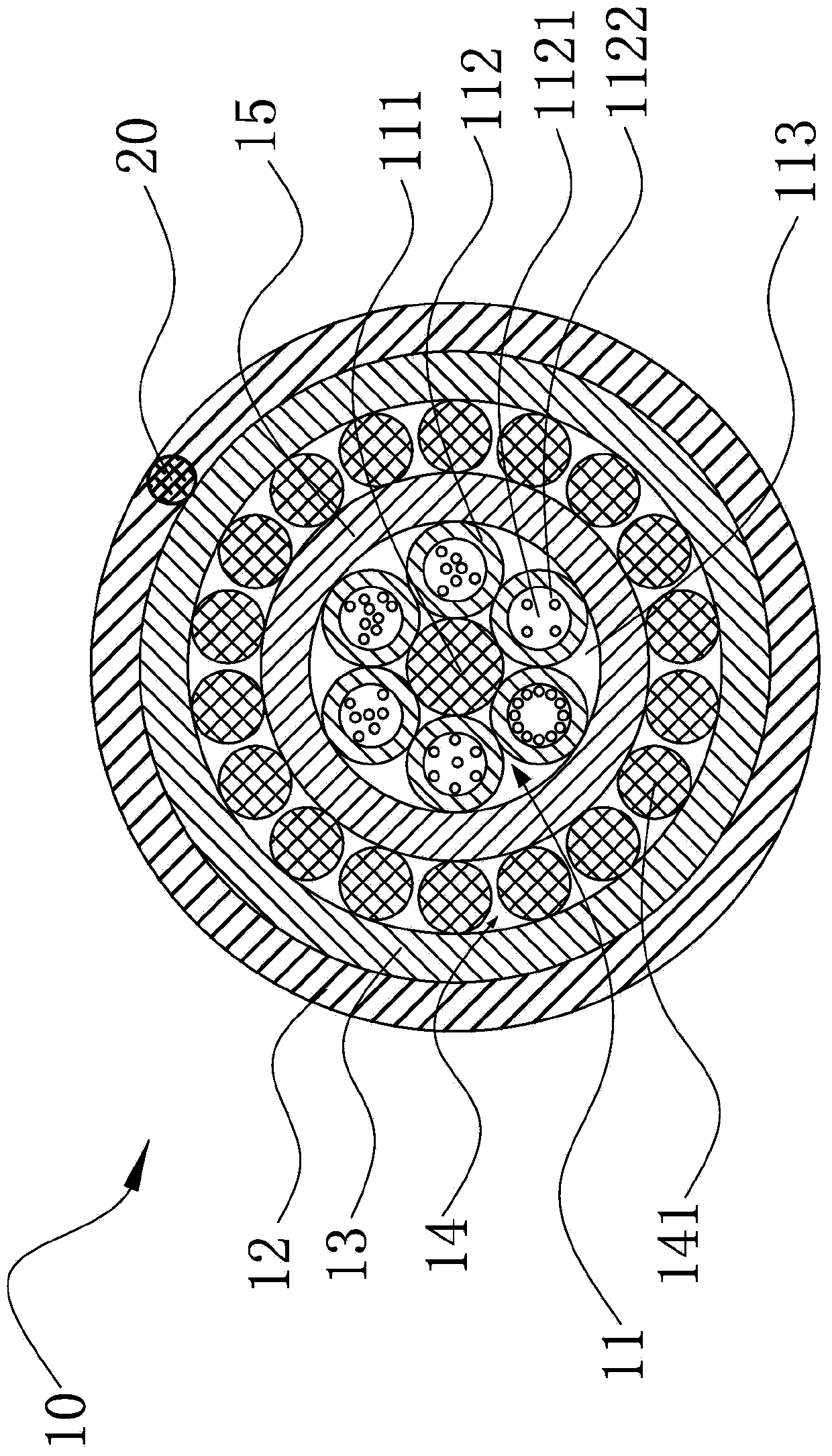
Novel non-metal layer-twisting mining optical cable
A non-metallic, layer-twisted technology, applied in the field of optical communication transmission, can solve problems such as communication interruption, optical cable damage, and potential safety hazards, and achieve the effects of avoiding lightning strikes, potential safety hazards, and low cost
- Summary
- Abstract
- Description
- Claims
- Application Information
AI Technical Summary
Problems solved by technology
Method used
Image

Examples
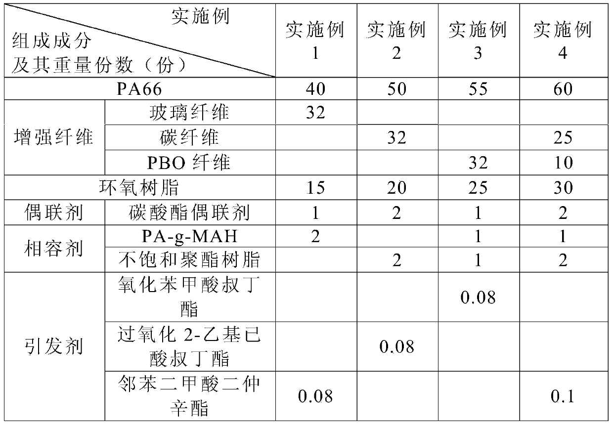
Embodiment 1
[0042] Weigh the glass fiber according to Example 1 in Table 1, carry out hot air oxidation treatment at 500°C for 2h, then weigh the carbonate coupling agent, and dip the glass fiber after hot air oxidation treatment in the carbonate coupling agent for 1h activation Then dry it at 100°C.
[0043] Then weigh PA66, epoxy resin, compatibilizer, initiator and the above-mentioned treated glass fibers, add them into a high-speed mixer and mix evenly, and then extrude and granulate in a twin-screw extruder to obtain FRP pellets. Wherein, the extrusion temperature of the extruder is 200° C., the feeding frequency is 30 Hz, and the rotational speed of the main engine is 300 rpm.
Embodiment 2
[0045] Weigh the carbon fiber according to Example 2 in Table 1, carry out hot air oxidation treatment at 500°C for 2h, then weigh the carbonate coupling agent, dip and activate the carbon fiber after the hot air oxidation treatment in the carbonate coupling agent for 1h Dry at 100°C.
[0046] Then weigh PA66, epoxy resin, compatibilizer, initiator and the above-mentioned treated carbon fiber, put them into a high-speed mixer and mix evenly, and then extrude and granulate in a twin-screw extruder to obtain FRP pellets. Wherein, the extrusion temperature is 200° C., the feeding frequency is 30 Hz, and the rotational speed of the host is 300 rpm.
Embodiment 3
[0048] Weigh the PBO fiber according to Example 3 in Table 1, carry out hot air oxidation treatment at 550°C for 1 h, then weigh the carbonate coupling agent, and dip the PBO fiber after the hot air oxidation treatment in the carbonate coupling agent for 2 h Then dry it at 120°C.
[0049] Then weigh PA66, epoxy resin, compatibilizer, initiator and the above-mentioned treated PBO fiber, put them into a high-speed mixer and mix evenly, and then extrude and granulate in a twin-screw extruder to obtain FRP pellets. Wherein, the extrusion temperature is 200° C., the feeding frequency is 30 Hz, and the rotational speed of the host is 300 rpm.
PUM
 Abstract
Description
Claims
Application Information