Electrical terminal ground structure and installation method

An electrical terminal and grounding structure technology, applied in the field of electrical terminal grounding structure, can solve the problems of unstable conductivity, inconvenient disassembly and maintenance, and difficult connection between electrical terminals and composite materials, and achieves grounding performance against pull-off force and meets performance requirements. effect of demand

Inactive Publication Date: 2014-08-20
MEISHAN CRRC FASTENING SYST CO LTD
View PDF8 Cites 8 Cited by
  • Summary
  • Abstract
  • Description
  • Claims
  • Application Information

AI Technical Summary

Problems solved by technology

[0003] The electrical terminal grounding structure and installation method provided by the present invention are aimed at solving the following problems in the existing electrical terminal

Method used


Image

  • Electrical terminal ground structure and installation method
  • Electrical terminal ground structure and installation method
  • Electrical terminal ground structure and installation method

Examples


Embodiment Construction

[0033] The electrical terminal grounding structure of this embodiment is composed as follows:

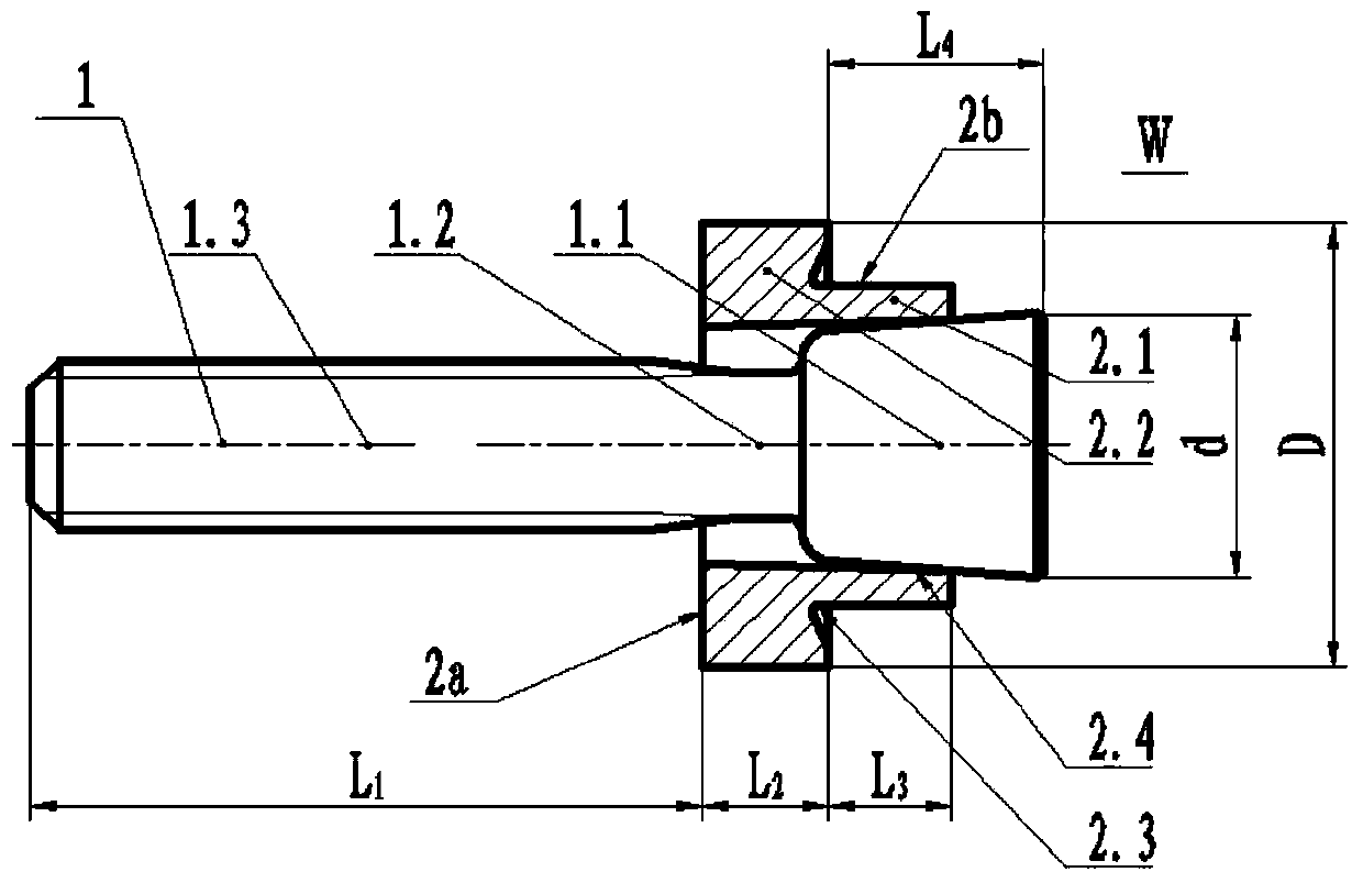
[0034] 1) see figure 1 , set the bolt 1 composed of a wedge-shaped head 1.1 at the front end, a transition polished rod section 1.2 in the middle and a threaded section 1.3 at the rear end, and the material is stainless steel. It is assumed that the collar 2 has a sleeve 2.1 at the front end, a flange 2.2 at the rear end and a groove 2.3 on the front face of the flange, and the material is aluminum alloy or copper alloy. The sleeve is sheathed outside the wedge-shaped head, and the inner hole of the sleeve is a wedge-shaped surface 2.4 with the same inclination as the wedge-shaped head.

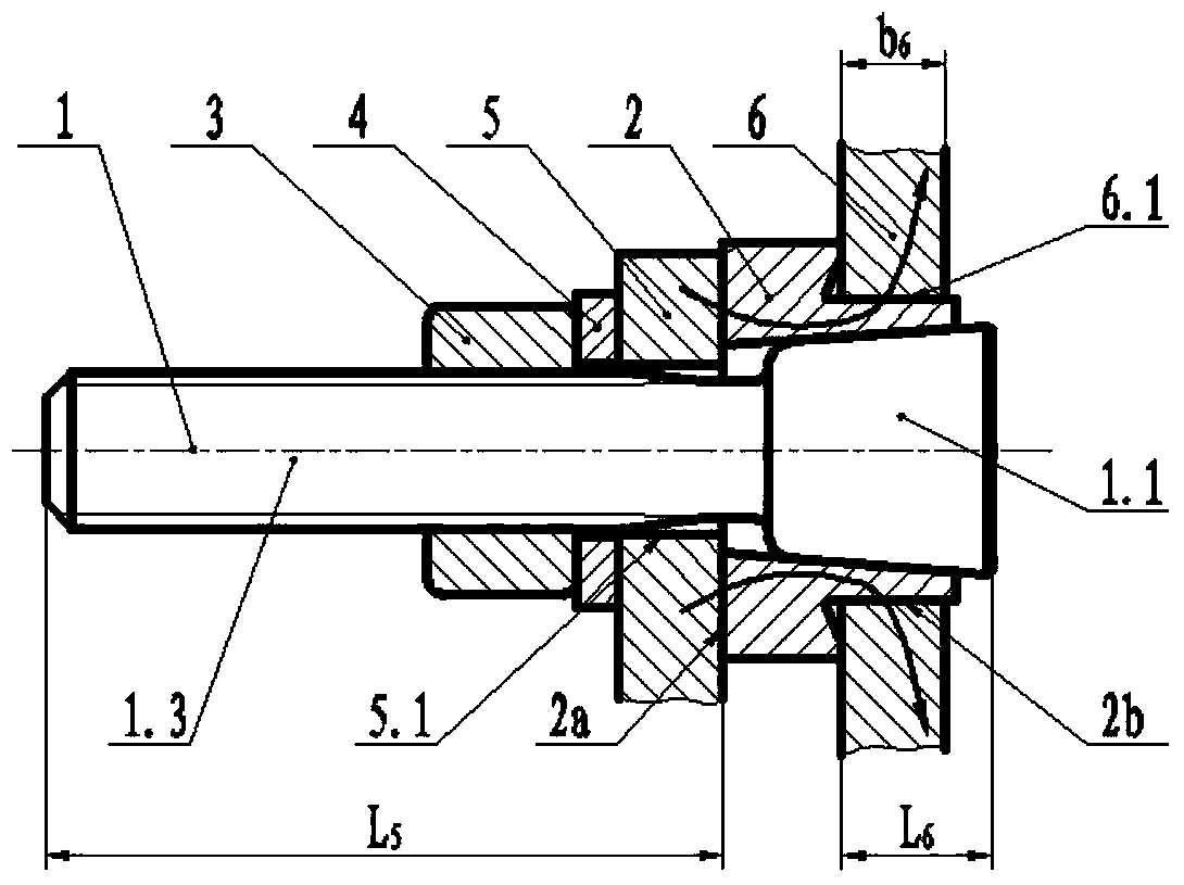
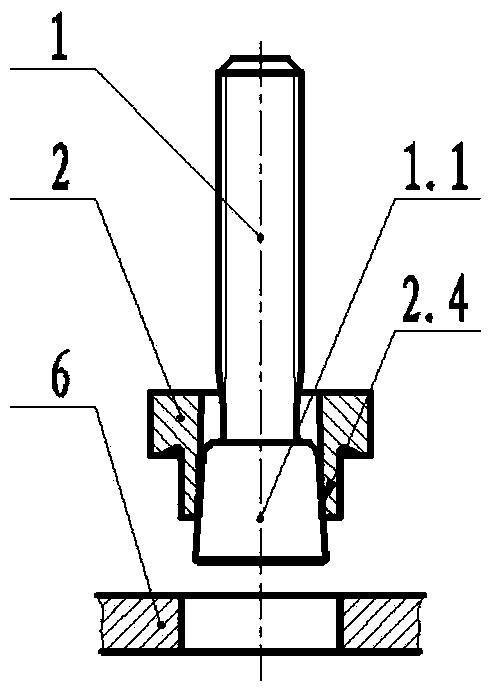
[0035] 2) see figure 2 , The outer circular surface 2b of the sleeve is placed in the mounting hole 6.1 of the grounding plate 6; the wedge-shaped head 1.1, the sleeve 2.1 and the mounting hole 6.1 are radially tightly fitted.

[0036] 3) see figure 2 , the electrical terminal 5 is set outsid...


PUM


Abstract

The invention discloses an electrical terminal ground structure and an installation method. The electrical terminal ground structure is characterized in that a bolt is provided with a wedge-shaped head and a threaded section, a shrink-ring is provided with a wedge-shaped face sleeve and a flange, and the wedge-shaped head is sleeved with the sleeve; the external round face of the sleeve is in tight fit with an installation hole of a ground plate in the radial direction; a lock nut and a spacer are installed outside the threaded section; an electrical terminal is axially installed between the flange and the spacer, and an axially screwed nut enables the electrical terminal to make tight contact with the flange of the shrink-ring. The bolt is made of stainless steel, and the shrink-ring is made of aluminum alloy or copper alloy. The installation method comprises the steps that after the surfaces of the bolt and the sleeve are processed, the wedge-shaped head is sleeved with the sleeve, the sleeve is inserted into the installation hole, the bolt is screwed in a riveting device for riveting, and then the bolt is sleeved with the electrical terminal and the nut until axial compression is achieved. The test shows that by the adoption of the structure and size optimization, the properties such as pulling-out force, rotational torque, leakage, a resistance value, impact resistance and vibration resistance can meet the requirements. The existing welding defects are overcome, the connection problem caused when an existing ground plate is made of a composite material is solved, and the electrical terminal ground structure is applied to high-speed trains, railway tracks, buildings and the like and meets the property requirement of ground structures under the complex conditions.

Description

[0001] (1) Technical field: The present invention relates to a structure for grounding electrical terminals, which is mainly used for fastening and connection of electrical terminals in the fields of high-speed trains, railway tracks, buildings and the like. It is a line connector (H01R). (two) background technology: [0002] At present, the electrical terminals of high-speed motor vehicles, railway tracks, buildings, etc. are mainly grounded by welding. Welding connections have high requirements for welding technology, and the welding process is prone to unstable quality, unstable electrical conductivity after welding, and inconvenient disassembly and maintenance. . At the same time, in some structures, carbon fiber composite materials are used to reduce the weight of the ground wire, and the connection between the electrical terminal and the composite material cannot be connected by welding. (3) Contents of the invention: [0003] The electrical terminal grounding structu...

Claims


Application Information

Patent Timeline
IPC IPC(8): H01R4/64H01R4/50H01R43/00
Inventor 赵祥云伏凯胡方年刘宇刘洋熊光连贾云龙代广成何旭
Owner MEISHAN CRRC FASTENING SYST CO LTD
Why Eureka
Try Eureka