Polarization coupler
A wave splitter and polarization technology, which is applied in the direction of waveguide devices, waveguides, electrical components, etc., can solve the problems of unobtainable performance and small adjustment margin of isolation boards, etc.
- Summary
- Abstract
- Description
- Claims
- Application Information
AI Technical Summary
Problems solved by technology
Method used
Image
Examples
Embodiment approach 1
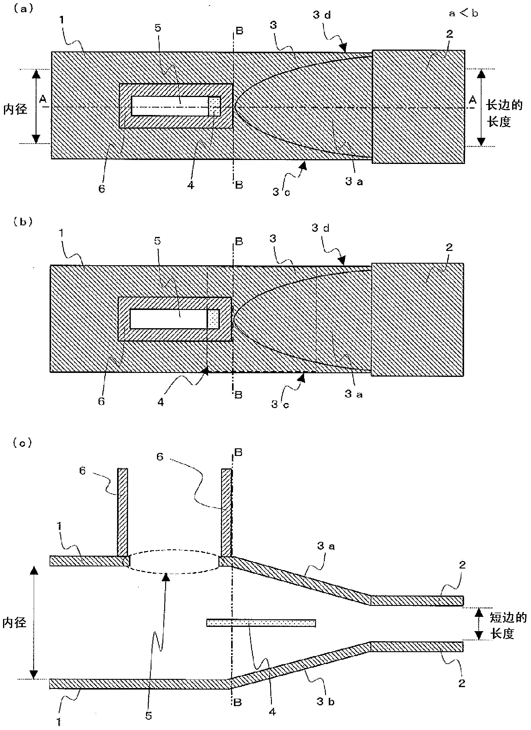
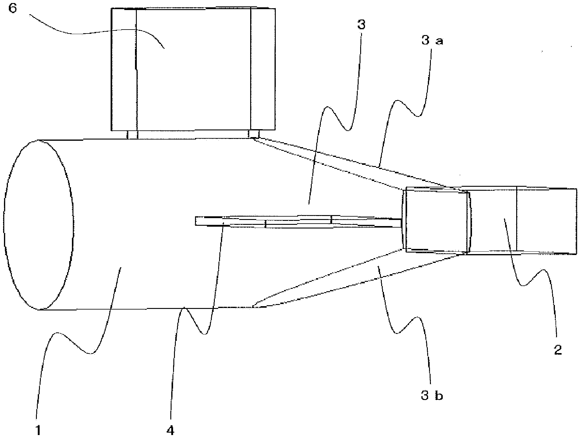
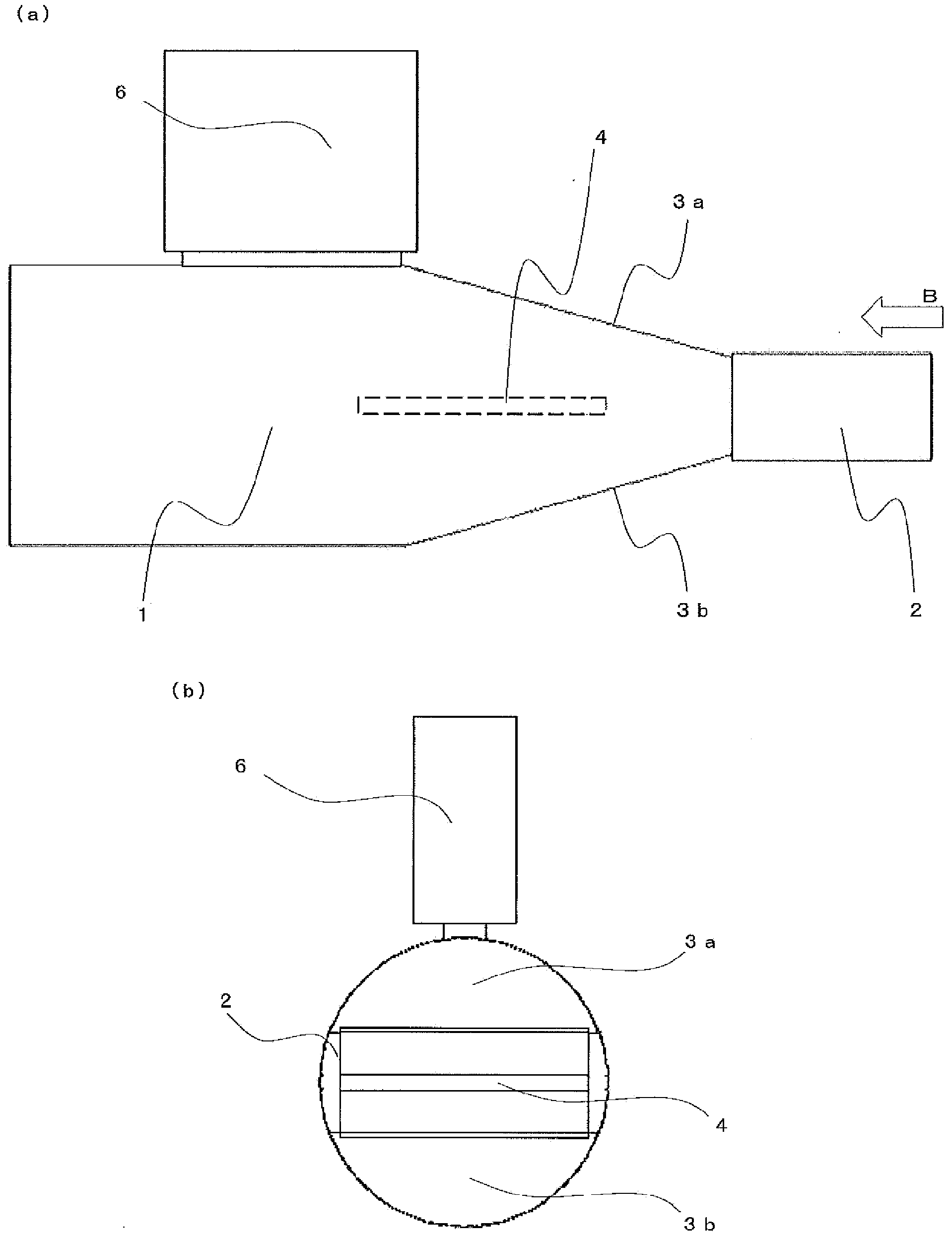
[0090] Next, use Figure 1 to Figure 7 Embodiment 1 of the present invention will be described. figure 1 (a) is a top view of the polarization splitter, figure 1 (b) is the top view of the polarization splitter (the conductor wall (isolation plate) is indicated by the dashed line), figure 1 (c) is along figure 1 (a) A cross-sectional view of the polarization splitter shown by the dotted line AA, figure 1 The double-dashed line BB in represents the boundary of the circular waveguide and the function connecting the waveguide. image 3 (a) is a perspective side view of the polarization split-wave diagram (conductor walls (separator plates) are indicated by dashed lines), image 3 (b) is from image 3 (a) A side view of the polarization splitter observed by the arrow B described above. In the drawings, the same symbols denote the same or corresponding parts, and thus detailed description thereof will be omitted.
[0091] Figure 5 (a) is a perspective top view of the polar...
Embodiment approach 2
[0111] use Figure 8 ~ Figure 12 , Embodiment 2 of the present invention will be described. Figure 9 (a) is a perspective side view of a polarization splitter (conductor walls (isolation plates) are indicated by dashed lines), Figure 9 (b) is from Figure 9 (a) The side view of the polarization splitter observed by the arrow B described, Figure 11 (a) is a perspective top view of the polarization splitter (the coupling hole and the square auxiliary waveguide are omitted), Figure 11 (b) is a perspective top view of the polarization splitter (the coupling hole and the square auxiliary waveguide are omitted), Figure 12 (a) is a perspective side view of a polarization splitter (conductor walls (isolation plates) are indicated by dashed lines), Figure 12 (b) is from Figure 12 (a) The side view of the polarization splitter observed by the arrow B described, Figure 12 (c) is along Figure 12 (a) A cross-sectional view of the polarization demultiplexer along the dotted ...
Embodiment approach 1 and 2
[0117] In the polarization duplexer according to Embodiments 1 and 2, the circular waveguide 1 and the connection waveguide 3 are preferably integrally formed by a common processing method such as cutting or die-casting. It is also preferable that the conductor wall 4 is integrally formed together with the circular waveguide 1 and the connecting waveguide 3 by a common processing method such as cutting or die-casting. In addition, the connection between the connecting waveguide 3 and the square waveguide 2 may be connected by a common waveguide connection method.
[0118] In the case where the circular waveguide 1 and the connecting waveguide 3 are integrated, in Embodiment 1, the connecting waveguide 3 can be interpreted as being connected to the square waveguide 2 provided on the circular waveguide 1 In the tapered transition portion at one end, the conductor wall (separation plate) 4 is arranged across the region of the circular waveguide 1 and the tapered transition portio...
PUM
 Abstract
Description
Claims
Application Information
 - R&D
- Intellectual Property
- Life Sciences
- Materials
- Tech Scout
- Unparalleled Data Quality
- Higher Quality Content
- 60% Fewer Hallucinations
Browse by: Latest US Patents, China's latest patents, Technical Efficacy Thesaurus, Application Domain, Technology Topic, Popular Technical Reports.
© 2025 PatSnap. All rights reserved.Legal|Privacy policy|Modern Slavery Act Transparency Statement|Sitemap|About US| Contact US: help@patsnap.com


