Al technical title is built by PatSnap Al team. It summarizes the technical point description of the patent document.
A water jet and vacuum cleaner technology, which is applied in the direction of vacuum cleaners, suction filters, cleaning equipment, etc., can solve the problems that the water jet pressure does not reach the preset target, the boosting effect is limited, and the running resistance is increased, so as to increase the friction factor and the effect Good, the effect of improving the dust collection ability
Inactive Publication Date: 2016-03-02
JIANGSU UNIV
View PDF4 Cites 0 Cited by
Summary
Abstract
Description
Claims
Application Information
AI Technical Summary
This helps you quickly interpret patents by identifying the three key elements:
Problems solved by technology
Method used
Benefits of technology
Problems solved by technology
However, in the actual use process, it was found that since the water flow directly enters the booster chamber, the running resistance is increased due to the weight of the water flow during operation, the booster effect is limited, the formed water jet pressure does not reach the preset target, and the overall efficiency of the system is still low. There is room for improvement
Method used
Image
Click on the blue label to locate the original text in one second.
Reading with bidirectional positioning of images and text.
Examples
Embodiment 1
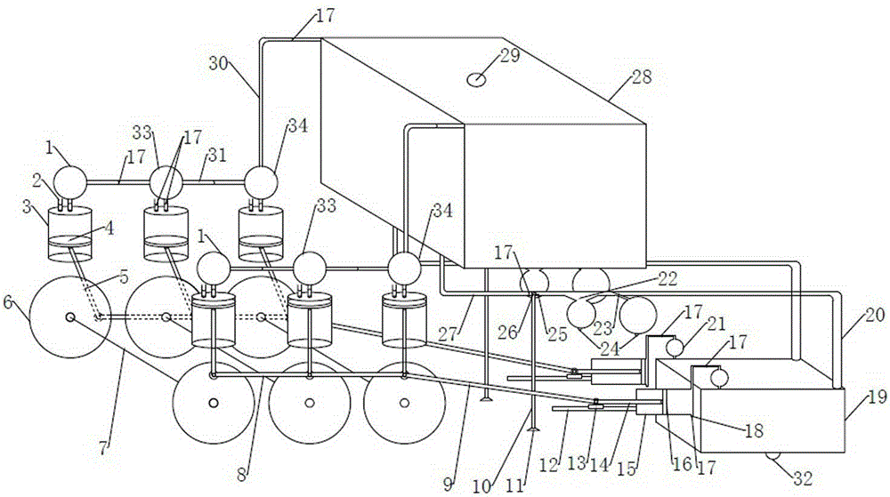
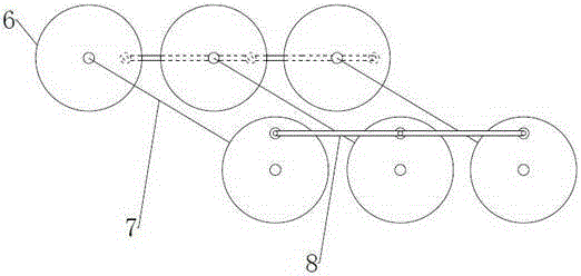
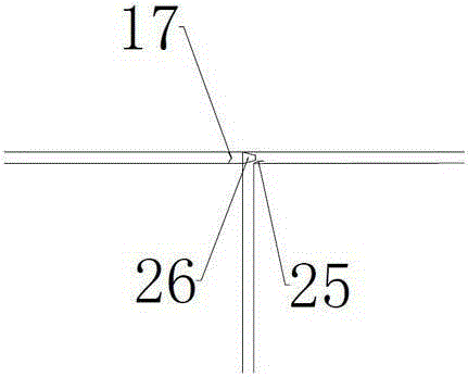
[0034] Such as figure 1 As shown, the pressure incremental water jet vacuum cleaner of the present invention includes a primary pressure storage chamber 1, an air suction hole 2, a booster chamber 3, a piston 4, a connecting rod 5, a driving wheel 6, a driving shaft 7, and a driving wheel connecting rod 8. Slider connecting rod 9, dust suction duct 10, dust suction port 11, sliding track 12, slider 13, negative pressure piston connecting rod 14, negative pressure generating chamber 15, negative pressure piston 16, one-way valve 17, exhaust Air hole 18, sewage collection chamber 19, sewage conveying pipe 20, anti-suckback chamber 21, vortex descaling chamber 22, garbage recovery chamber 24, nozzle 26, pressurized clean water conveying pipe 27, water tank 28, water injection port 29, high pressure Delivery pipe 30 , pressure delivery pipe 31 , garbage discharge port 32 , secondary pressure storage chamber 33 , and tertiary pressure storage chamber 34 .
[0035] Driving wheel 6 is...
PUM
Abstract
The invention relates to the technical field of mechanical dust removal, in particular to a pressure-increasing water jet vacuum cleaner, which includes a primary pressure storage chamber, an air suction hole, a booster chamber, a piston, a connecting rod, a driving wheel, a driving shaft, a driving wheel connecting rod, Slider connecting rod, dust suction duct, dust suction port, sliding track, slider, negative pressure piston connecting rod, negative pressure generating chamber, negative pressure piston, one-way valve, exhaust hole, sewage collection chamber, sewage conveying pipe, Anti-suckback chamber, vortex descaling chamber, garbage recovery chamber, nozzle, pressurized water delivery pipe, water tank, water injection port, high-pressure delivery pipe, pressure delivery pipe, garbage discharge outlet, secondary pressure storage room, tertiary pressure storage The invention does not use other energy sources such as electric energy, and can be used without a power supply. It mainly relies on the movement of the drive wheel, drive shaft and drive wheel connecting rod in the process of moving the vacuum cleaner, and the driving of the connecting rod drives the piston to pressurize the water flow to form a vacuum cleaner. The main power of the water jet vacuum cleaner.
Description
technical field [0001] The invention relates to the technical field of mechanical dust removal, in particular to a novel water jet low-carbon and environment-friendly vacuum cleaner device. Background technique [0002] At present, vacuum cleaners are mainly composed of three parts: dust collection, dust collection, and dust filtration, generally including series commutator motors, centrifugal fans, dust filters (bags) and dust collection accessories. The power of a general vacuum cleaner is 400-1000W or higher, and the power of a portable vacuum cleaner is generally 250W or less. [0003] The vacuum cleaner can remove dust mainly because its "head" is equipped with a fan. There is a wind impeller on the rotating shaft of the fan. After the power is turned on, the fan will generate strong suction and pressure at a high speed. The air in the vacuum cleaner creates an instantaneous vacuum inside the vacuum cleaner, forming a negative pressure difference with the outside atmo...
Claims
Application Information
Patent Timeline
Application Date:The date an application was filed.
Publication Date:The date a patent or application was officially published.
First Publication Date:The earliest publication date of a patent with the same application number.
Issue Date:Publication date of the patent grant document.
PCT Entry Date:The Entry date of PCT National Phase.
Estimated Expiry Date:The statutory expiry date of a patent right according to the Patent Law, and it is the longest term of protection that the patent right can achieve without the termination of the patent right due to other reasons(Term extension factor has been taken into account ).
Invalid Date:Actual expiry date is based on effective date or publication date of legal transaction data of invalid patent.