High-temperature electrostatic precipitation system

An electrostatic dust removal and high temperature technology, applied in the field of environmental protection dust removal equipment, can solve the problems of low dust removal efficiency of the cyclone dust collector, large pressure loss of the dust collector, and large operating resistance, so as to improve the quality of subsequent condensed tar and other gasification products , Purify gas, improve energy efficiency

Active Publication Date: 2014-08-27
ZHEJIANG UNIV
View PDF7 Cites 19 Cited by
  • Summary
  • Abstract
  • Description
  • Claims
  • Application Information

AI Technical Summary

Problems solved by technology

The dust removal efficiency of the cyclone dust collector for dust removal based on the principle of inertial collision is not high, and it is usually used for pre-collection of dust, and the viscosity of the gas increases after the temperature rises, and the dust removal efficiency is lower than that of normal temperature; Gas purification has high air tightness requirements, high pressure loss makes the design more difficult, and the dust cleaning process of filter type dust removal needs to be blown back, and the drastic change of pressure at high temperature will easily lead to the damage of the filter material
[0006] The patent with the publication number CN101559307 discloses a high-temperature-resistant dust collector that can operate continuously at 300-1000°C. It uses a metal filter cartridge instead of a bag filter cartridge to withstand high temperatures. The dust collector has high dust removal efficiency, high operating resistance and Low energy consumption, but its metal filter cartridge is made of high-temperature-resistant metal material, which is expensive and has a large running resistance (usually above 15kPa), which greatly increases the design and cost of the dust collector

Method used


Image

  • High-temperature electrostatic precipitation system
  • High-temperature electrostatic precipitation system
  • High-temperature electrostatic precipitation system

Examples


Embodiment Construction

[0024] The present invention will be further described below in conjunction with the accompanying drawings and specific embodiments, but the protection scope of the present invention is not limited thereto.

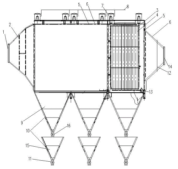
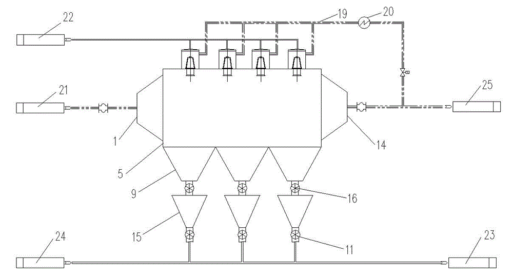
[0025] refer to Figure 1~3 , a high-temperature electrostatic precipitator system, the system includes a gas inlet 1, a dust collector housing 5, a gas outlet 14 and a layered ash hopper, the left and right ends of the dust collector housing 5 are respectively connected to the gas inlet 1, the gas The outlet 14 is connected, and the lower end of the dust collector housing 5 is connected with the layered ash hopper. The connection between the gas inlet 1 and the dust collector housing 5, and the connection between the dust collector housing 5 and the layered ash hopper are all equipped with corresponding room for expansion. The expansion space is set according to the required temperature range and shell size. Taking 800°C as an example, a thermal expansion space with a t...


PUM


Abstract

The invention relates to a high-temperature electrostatic precipitation system. The high-temperature electrostatic precipitation system comprises a gas inlet, a deduster housing, a gas outlet and a layered ash bucket. Left and right ends of the deduster housing are respectively connected to the gas inlet and the gas outlet. The lower end of the deduster housing is connected to the layered ash bucket. An anode plate and a cathode rod are arranged in the deduster housing. A sealing housing is arranged around the deduster housing. A cavity is formed between the sealing housing and the deduster housing. Alumina porcelain is used for insulation between the cathode rod and the deduster housing. The alumina porcelain is connected to a hot air purging device. The bottom of the anode plate is provided with a mechanical vibration device. The periphery of the layered ash bucket is provided with a thermal insulation device. The layered ash bucket comprises an upper ash bucket and a lower ash bucket. The upper ash bucket is connected to the deduster housing. One end of the lower ash bucket is connected to the upper ash bucket by a cindervalve and the other end of the lower ash bucket is connected to an ash bucket pneumatic conveying device. The high-temperature electrostatic precipitation system can guarantee that the electric deduster effectively gathers fine particles in cracking gas at a high temperature of 300-800 DEG C and realizes equipment operation resistance less than 600Pa.

Description

technical field [0001] The invention belongs to the technical field of environmental protection dust removal equipment, and in particular relates to a high-temperature electrostatic dust removal system. Background technique [0002] Coal pyrolysis gasification technology is an important means of efficient and clean utilization of coal. By pyrolysis and gasification of coal rich in volatile matter at high temperature, gas and tar can be obtained, and gas and tar can be obtained through further deep processing High-quality fuel and chemical products, the semi-coke produced by pyrolysis can be used for combustion or gasification, so as to realize the graded and quality utilization of coal. Coal pyrolysis technology can make full use of a large amount of bituminous coal and lignite resources in my country, and can reduce the environmental pollution caused by coal burning while increasing the utilization value of coal. It has broad application prospects. At the same time, my cou...

Claims


Application Information

Patent Timeline
Patent Type & Authority Applications(China)
IPC IPC(8): B03C3/04B03C3/76B03C3/47B03C3/70B03C3/34
Inventor 高翔郑成航骆仲泱岑可法倪明江王毅张涌新方梦祥王勤辉肖刚施正伦周劲松程乐鸣王树荣余春江王涛
Owner ZHEJIANG UNIV
Why Eureka
Try Eureka